
| |
 |
My
Arrow-Style VHF/UHF Portable Satellite
Antenna
One of the pleasure of
working the amateur radio satellites is making
contacts in a portable application and with
QRP power. This requires a VHF/UHF handheld FM
radio and a handheld 2-band antenna. I
recommend that you consult the links above
before proceeding with the reading of this
web page, as I make implicit references to
those designs.
FEATURES So after reading and thinking, I came up with this improved "Arrow-Style" VHF/UHF antenna. The resulting antenna has the following characteristics:
The antenna performance should
match or surpass the Arrow
antenna. The UHF section is made of 6
elements with gain-optimized spacing as
opposed to 7 elements with equal spacing for
the Arrow. This makes my antenna shorter by
6 inches. The antenna is lightweight, only
19 ounces (550g).
Have you looked at the price of the original Arrow antenna? How about working on this evening project and spending only 1/3 the cost? CONSTRUCTION Element Lengths and Positioning The suggested boom length is 30 inches. Since the UHF antenna is the longest of the the two, the 4th Director (Dir.4) should start close to the tip of the boom. By measuring 24 inches back from that position, it will give you the position for the Reflector (Refl.) element. This leaves roughly 6 inches for the handle. As for the VHF antenna, its Reflector element can be positioned forward of the UHF Reflector by 3/4-inch. The table below summarizes the element dimensions and spacing for frequencies of 146.000MHz and 435.000MHz. I suggest you cut the two driven elements a bit longer and then tweak the SWR by trimming the element tip. Use a hard cylindrical object of the right diameter to fold the Driven elements.
Boom Drilling Technique
Care must be used when drilling element holes on a circular boom. I found it almost impossible to drill element holes that would yield elements that are parallel and in the same plane, without using some form of guidance and reference. My trick for getting parallel elements is to first screw down the boom at both ends against a narrow wooden plank or board, and to use a vertical drill press to make the holes. 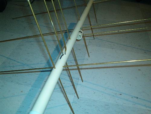 VHF Driven Element Fastening Since the boom has only a 7/8-inch outside diameter, I added another short piece of pipe to support the folded portion of the VHF Driven element. I used 2 self-tapping screws to fasted the piece of pipe to the boom. (see picture below). UHF Driven Element Fastening The UHF Driven element has a gap of only 1/2-inch, so bending the feedpoint end of the folded section to create a 1/4 inch gap is manageable and allows to support the element without adding another short piece of pipe like for the VHF Driven element. Element lengthening If, like me, the only length of brass rod available to you is 36 inches, you will need to lengthen each of the VHF elements by splicing two brass rods together. A good way to do this is by filing off half of the rod thickness for about 1/2 of an inch long at each end with a grinder. Then, position the two ends one against the other and solder the two rods together using a gas torch or a powerful soldering gun. The end result is illustrated below.  VHF Feedpoint Connection
The feedpoint connection to the VHF Driven element is done in such a way that it can be disconnected if the antenna is to be disassembled for travelling, which will be the case for most situations. I use DIP integrated circuit socket pins for the mating. You need a DIP socket of the machined type, the kind that has barrel contacts. Using a sharp knife, cut the plastic to detatch 4 pins from their socket. Solder two pins with their barrel end facing the coaxial cable. Solder two pins to the coaxial cable with the pin ends facing the driven element. This is a temporary but effective connection.Connect the coaxial center conductor to the folded section end and the shield to the long section.See the picture below. Other means of connecting can be used. 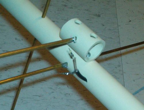 Since I don't intend to disassemble the UHF section, the feedpoint connection for the UHF Driven element is more straightforward. I simply split the coaxial center conductor and shield. Again, I solder the coaxial center conductor to the folded section end and the shield to the long section.  Microduplexer Since most handheld dual-band radios have a single antenna connector (VHF and UHF signals are combined), you will need an antenna duplexer. A commercial duplexer will work fine, but is quite heavy. Remember that you will have to point this antenna by hand for 15-minute satellite passes. Because of this, I elected to build the Microduplexer. I have the capability to make my own PCBs, so I tried to obtain the original layout from the author. It appears that the final layout in a ready-to-make form is no longer available. So I re-imported the Autocad DXF file, re-worked the proposed layout, filled the islands, etc. The final Microduplexer board layout is available below. Printing the PDF file with 100% scaling will give accurate results. I also provide a Gerber file for those who would like to have the PCB professionally made. Note that in order to fit the Microduplexer PCB inside the CPVC boom, I had to file off a bit of both long edges of the PCB. I did this before installing the components.
Coaxial Cable Runs I run the coaxial cables inside the boom. I drill holes at an angle, close to the feedpoints, where I bring out the coax (see pictures). The Microduplexer is located inside the boom, within the handle portion. this is where the three coaxial cables converge. I bring out the transceiver feedline at the back of the handle.  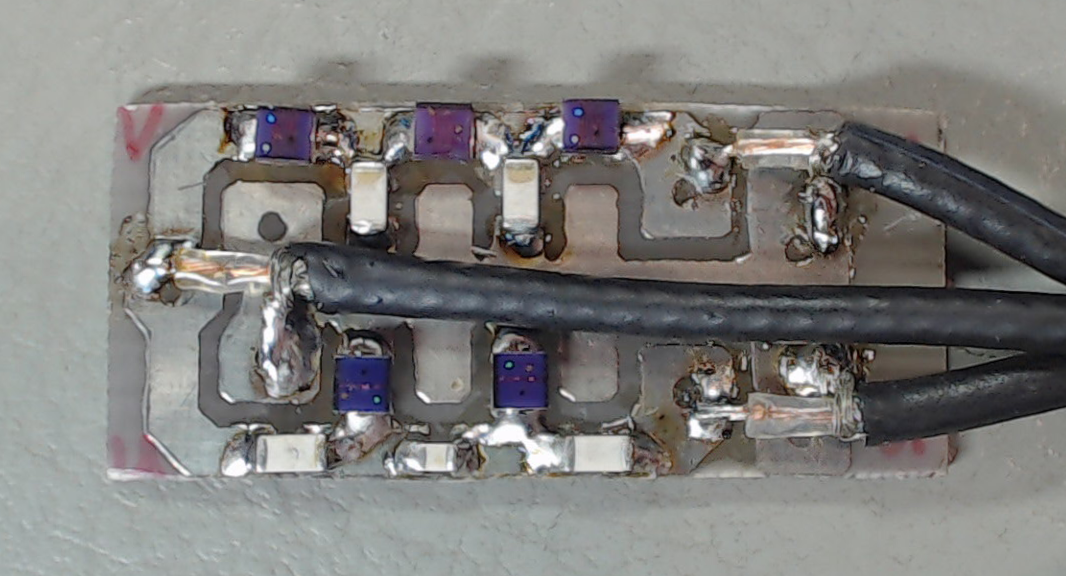 Other Considerations
RESULTS During operation, the results have been quite gratifying so far. The VSWR is at less than 1.5:1 on both bands. I have no problem working AO-51 pretty much from horizon to horizon. Of course, some "big guns" will swamp my signal every now and then, but that is not due to the antenna, but rather to the 2 Watts of RF output I use on the uplink. The cool thing I did this summer was to bring my portable setup to our camping trip...So much fun when wife and kids are gone on a bike ride! PARTS LIST
|