|

|
|
Combined 432 MHz
High-Pass
/ 144 MHz
Notch Filter
By: Bertrand
Zauhar, VE2ZAZ
Page last
updated: 02/04/2012
This
page presents the design and construction of a combined 432MHz
High-Pass
/ 144MHz Notch filter. This filter is to be left permanently on the
70cm
antenna coaxial cable to notch out the 2m RF energy that could damage
the 70cm receiver front end.
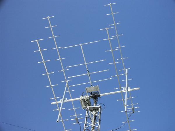
This
filter, along with the reciprocal 144MHz Low-Pass
/ 432MHz Notch filter, became a requirement for my station
because I co-located a 2m yagi within an EME array of four 70cm
yagi antennas. See the picture on the right. Antenna simulations and
experience have shown that the 2m yagi will cause negligible
deterioration of the 70cm EME array performance as long as it is
positioned exactly in the center of the four 70cm yagis.
Still, as I had expected, the coupled 144MHz RF energy into the 70cm
yagis was higher than what a typical receiver front end could tolerate.
I actually measured 10mW at the 70cm antennas when transmitting 100W
into
my 2m EME array. This is a -40dB coupling between antennas. It is
actually better than what I had expected, but it is still
probably too much for the 70cm mast-mounted preamp to cope with. Maybe
there is a LC high-pass filter at the input of my 70cm preamp, but I
did not want to try it!
Hence the need for a
filter. A high-pass filter combined with a notch filter appeared to me
as a good way to do this. A commercial diplexer might have done the
trick, but I did not want to spend, I wanted to build!
The main design objectives were:
- At least 30dB of attenuation of
the 144MHz signal.
- Minimal insertion loss (S21) at
432MHz, < 0.15dB
- Low VSWR (S11 or return loss)
at 432MHz, < 1.5:1
- Be able to support at least
100W of 144MHz RF, though my immediate use is Rx only.
The
design
activity was a combination of theory, gut feeling and trial-and-error. The resulting filter
circuit
consists of a high-pass filter stage (C1, L1, C2) followed by a
Series-LC notch
filter stage (L2,C3). This is shown on the figure to the right.
Simulations were performed using Ansoft
Serenade SV v8.50. I used a Q (quality factor) of 50 for the inductors
and 500 for the capacitors. The resulting simulation plots are shown on
the right. With these results on hand, it was time to heat up the
soldering iron!
|
Click
on
the figure to
enlarge it.
Click
on
the figure to
enlarge it.
|
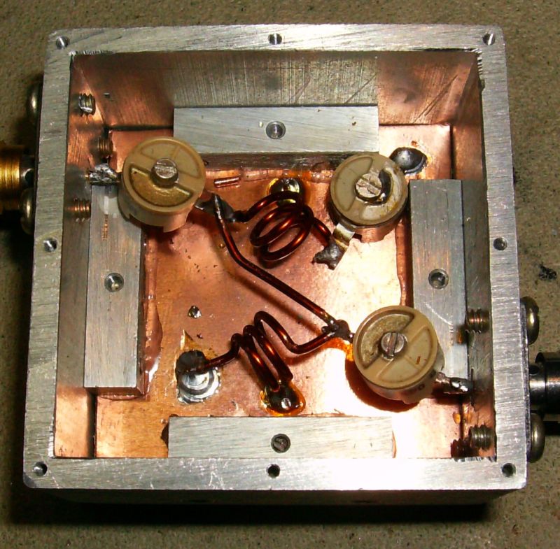
For
the enclosure, I used a square aluminum box on which I installed two
SMA-female bulkhead connectors. This enclosure did not have
compartments which could have improved isolation between filter stages,
but I decided to give it a try.
You may build a box using PCB material
or use an
off-the-shelf enclosure. This is not really critical. I would pick a
large enough box so that the inductors do not come too close to the
walls.
The
variable capacitors I used are of
350V ceramic type .
These should work fine with a 432MHz RF power of at least 100W. The suggested capacitance
ranges are written on the circuit schematic.
As for the
inductors, their values and construction details are also
provided on the schematic above. I used enameled copper wire, but bare
copper wire will work the same. Of course, never use stranded wire for
winding coils... I recommend you mount the two inductors at right angle
one from the other to reduce coupling.
Update
02/04/2012: One ham with keen eyes spotted a mis-wiring of the circuit
in the enclosure shown on the right. Note that, even though the 144 MHz
notch filter part made of L2 and C3 is not connected to the right
location, it behaves exactly the same way: notch out the 144MHz signal
and get out of the way at 432 MHz.
|
Click
on
the figure to
enlarge it.
|
The
tuning of this
filter consists of first nulling the notch filter by using a 144MHz
signal source (RF generator level below 1mW or 0dBm) and an RF power
meter or 144MHz receiver. Adjusting C3 for minimum signal is the
objective. L2 winding spacing can also be changed and C3 re-adjusted
to make sure that the best null can be achieved. Tuning is quite sharp,
so go gentle on the tuning screwdriver. Using an RF power meter and a
signal generator could be tricky as the power meter will also pick up
the generator's harmonic spurs at 288MHz and 432MHz. A double check
with a 144MHz receiver or a spectrum analyzer is probably a good idea.
The second step in the tuning process consists of minimizing the VSWR
at 432MHz. This is done by tuning C1 and C2 for best VSWR when a 432MHz
transmitter is connected to a dummy load or antenna through the
filter. Use a low enough power to minimize the risk of transmitter
damage. If a good VSWR cannot be achieved, change L1 winding spread and
re-tune C1 for best VSWR.
Expect little interaction between the two filter stages. But as a final
pass, the above two steps should be repeated so that any interaction,
even small, between the two filter stages is taken into account.
The resulting performance should resemble what I have measured on my
filter. This is shown on the three figures on the right hand side. The
first figure shows
the
resulting notch
at 144MHz, a depth of greater than 60dB. The second figure highlights the very small
insertion loss at 432MHz. I
measured less than 0.1dB. The third figure shows the S11
reflection loss of better than -30dB at 432MHz. This is effectively a
1:1 VSWR.
With such a filter, I don't feel nervous for my 70cm preamp if I feed
100W or more
at 144MHz into my 2m antenna. This filter paired with the complementary
VHF Low-Pass /
UHF Notch filter allow a very safe and compact antenna
configuration.
|
Click
on
the
figure to
enlarge it
Click
on
the
figure to
enlarge it
Click
on
the
figure to
enlarge it
|
|
