|
|
 |
Si5351-based Clock Synthesizer board By: Bertrand Zauhar, VE2ZAZ
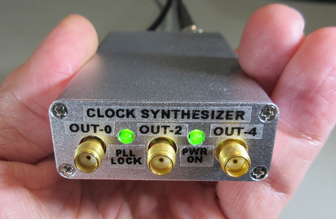
On this page, I describe my design of a
multiple output RF clock synthesizer board
based on the Silicon Labs Si5351 chip. This
integrated circuit provides a cheap and easy
way of producing up to six independent clock
outputs with frequencies ranging from a few
KHz to more than 200 MHz. This board
supports both the A and C version Si5351
chips, the latter being more valuable as it
allows to synchronize to an external
reference. If soldering a fine-pitch
leadless QFN package C version chip is not
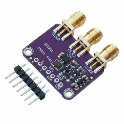
possible, the
builder can instead equip the board
with an off-the-shelf Chinese-made
Si5351A mini-module, and use the
board in free-running mode.
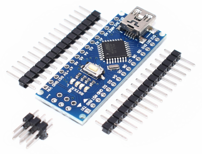
This board includes an external reference scaling/shaping circuit, which provides the proper amplitude to the Si5351C, regardless of the shape or amplitude of the input signal. Since the Si5351 chip configuration is volatile (configuration lost when power is removed), an accompanying micro-controller is required to re-program the chip at power up. I chose an Arduino Nano to perform this task. In order to create the desired Si5351 configuration for the Arduino, I also developed Python language computer scripts (programs) (simple-mode and manual-mode versions) that provide the ability to define the parameters and perform the transfer. These can run on Linux, Windows and Mac OS.
The best way to understand what this project offers is by first consulting the Circuit Schematic of the board below (click on image to enlarge): 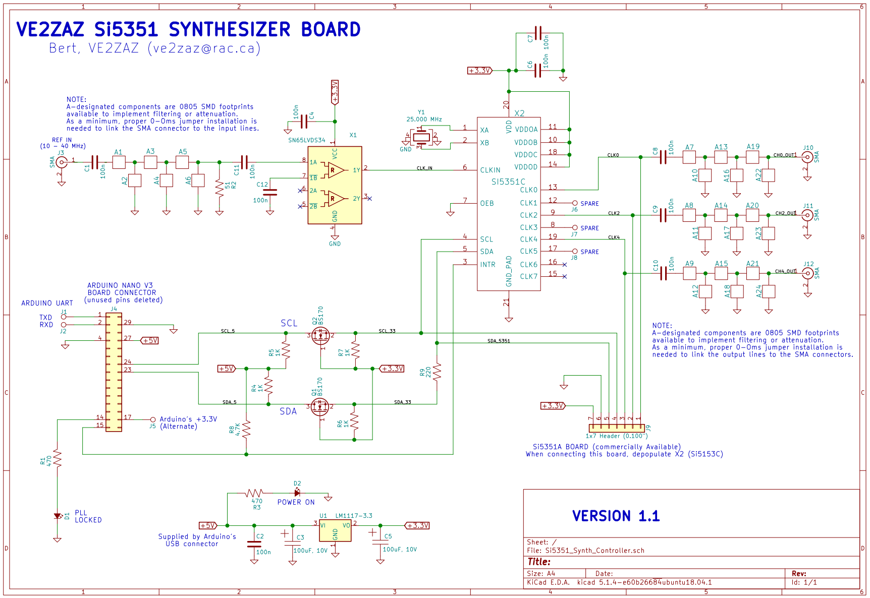
The circuit is rather
straightforward. The main features of this
printed circuit board are:
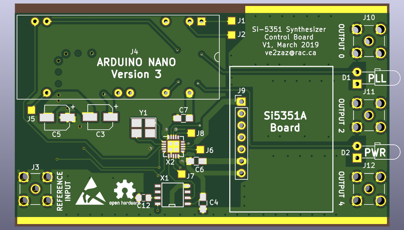
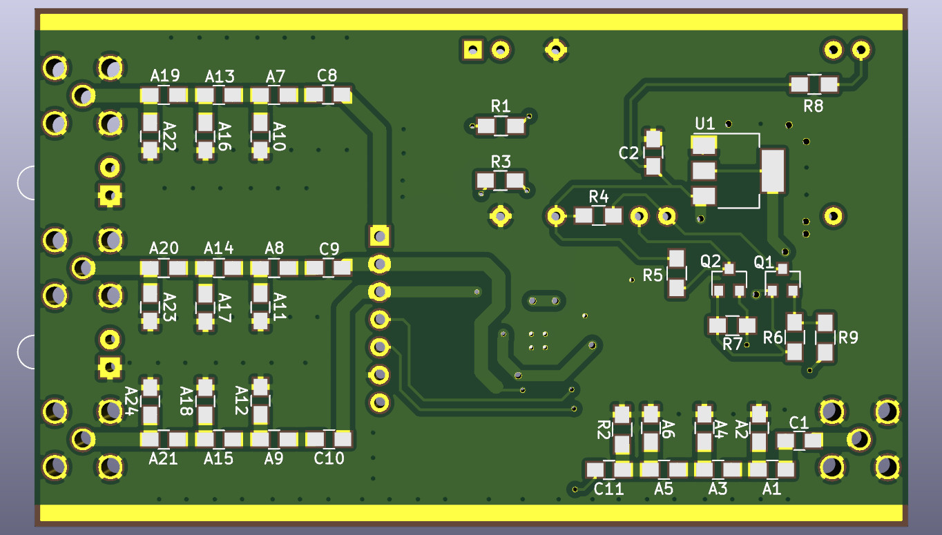
The Printed Circuit Board is a double-sided design with plated-through holes, solder resist and silkscreen (marking) on both sides. I provide the design files, and the gerber and drill files for anyone who would like to replicate it. Such PCB can be ordered for around 20$ per lot of 10 PCBs. Simply provide the gerber files and the drill file to the manufacturer. I ordered from JLCPCB, but other manufacturers should produce the same quality. In your order, select 0.062" (1,6 mm) thickness FR-4 glass-epoxy material, the standard stuff.
The following is a list of all required components and sub-modules to put together this project. Note that a number of components are required only when the Si5351C option is used. Components that are required in both Si5351C and Si5351A options are shown in bold font. Some procurement recommendations are provided in the right hand side column. Other than the details provided, part selection is not critical.
Early on, the builder must decide whether an Si5351C chip or the Si5351A mini-module will be used. If the mini-module is selected, a number of components can be omitted. The components that are required in all situations are shown in bold font in the component table above. One major challenge in assembling this board is the Si5351C soldering, which requires a hot-air rework station, some magnifying apparatus (camera or microscope), some soldering flux and a lot of skill. This is one VERY SMALL package! If you have never soldered this kind of device (QFN leadless), I recommend that you document yourself on the Internet prior to performing the work, or find someone who is willing to help with that task. This is an expensive chip, and you do not want to spoil it! The remaining of the board is not particularly difficult to assemble by hand if you can handle common surface-mounted components. A magnifying lamp, a fine tip soldering iron and a pair of tweezers are required. The lowest profile components should be installed first, starting with the Si-5351C chip, followed by the
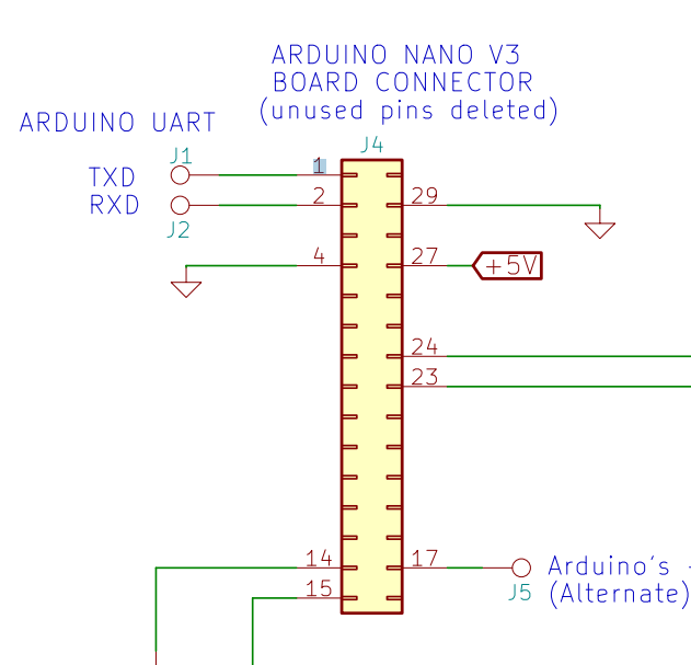
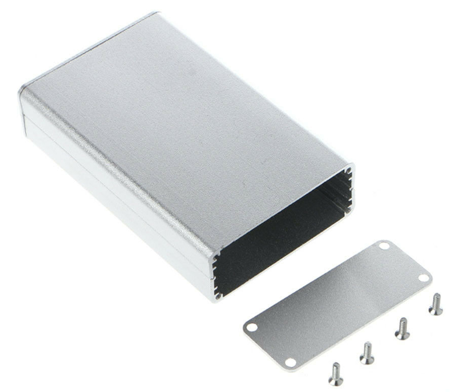
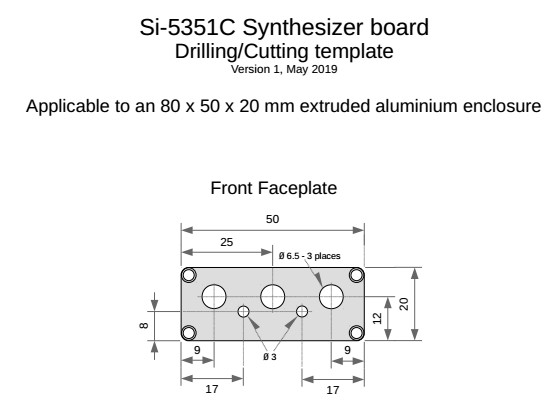
Prior to installing the Arduino Nano, its unused pins must be removed (or cut off flush) from the two rows of pins. Only the pins shown on the circuit schematic should be kept (see figure to the right). When preparing the Si5351A mini-module for installation on the board, do not solder the three SMA connectors on the mini-module. Output signals get extracted through the 7-pin header and are sent to the board's three SMA connector instead. The suggested enclosure is an 80 x 50 x20 mm extruded aluminum enclosure. The PCB dimensions were set for an exact fit into this enclosure. This two-sided clam shell enclosure can be easily found on most electronic component sites (eBay, AliExpress, Banggood...) for a few dollars. I provide a template drawing to help drill and cut the various holes on the front and rear faceplates.
The Arduino firmware (a.k.a. the sketch) is written to be compiled in the Arduino IDE environment. The Arduino sketch uses Jason Mildrum's Etherkit Si5351Arduino library (https://github.com/etherkit/Si5351Arduino). That library must be installed in the Arduino IDE via the Library Manager (Menu: Sketch -> Include Library -> Manage Libraries...) prior to compiling the sketch. The Arduino must be sent an Si5351 configuration from the software described below, otherwise the synthesizer board will not operate.
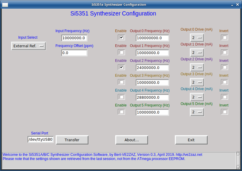
This software includes comprehensive help files (About.html and About_Raw.html) that describe the prerequisites, the installation process and the operation in detail. Please refer to the software package content to get these files. The software allows to
configure the Si5351A/B/C Synthesizer chip
when supervised by the Arduino Nano. Once
the Arduino has received a configuration
from this software, it will re-load the
Si5351 chip with that same configuration
at every power up or reset. The Arduino
(properly configured by this software) is
required as the Si5351 chip does not
retain its configuration when power is
removed; it must be re-configured at power
up.
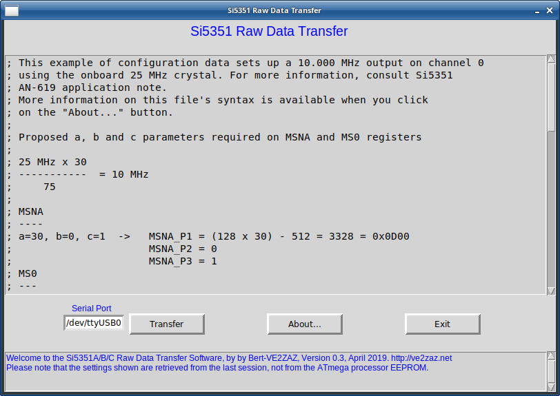
The software is written in Python 2.7 programming language. Thus it is fully compatible with the Linux and Windows (7, 8, 10) operating systems. Although it has not been tested, the software should also run properly on the Mac OS. The software covers a superset of features offered by the Si5351 family of chips. The user must understand the limits imposed by the Si5351 model (A or C version), such as the number of channels available or the support for an external reference input. A good comprehension of the Silicon Labs' Si5351 Datasheet document is recommended. The software is actually made of two python scrips. The "Si5351 Synthesizer Configuration" script was designed with the objective of exploiting the most common Si5351 features. Thus, it allows to configure the chip for most applications, but not all of them. Examples of features that are not implemented are VCXO support (the Si5351B chip), phase adjustment (other than simple inversion) and support for output channels 6 and 7. In an application where one or more of the missing features is required, the user can still use this hardware by programming the Arduino Nano using another python script, the "Si5351 Raw data Transfer" program. That Python script is also included in the package. In such case, various Si5351 registers will need to be programmed separately, which is more tedious. Obviously, the accompanying Arduino firmware (sketch) must be used in conjunction with this software, otherwise the latter will not function. The sketch is designed to interact with both versions of computer python scrips described here. Access must be granted to the computer's virtual serial port associated with the Arduino's serial-USB adapter, otherwise an error message will be displayed. The software
for the synthesizer board can be
obtained on GitHub by clicking on the
link below.
One cool
application of this Si5351 Clock
Synthesizer is a QRSS (very slow transmission
rate) low power Beacon transmitter. I
have put together the proper software and
Arduino firmware to
accomplish this task. Please
refer to this GitHub
link for more
information on implementing
the beacon.
The output clock shape generated by the Si5351 chip is a square wave. One must include proper lowpass or bandpass filtering if the output is to be used in radio applications, especially if it is to be used as a low power transmitter connected directly to an antenna. |