|
Kenwood TS-2000X 1.2GHz Tx Distortion problem and fix By: Bertrand Zauhar, VE2ZAZ The
Kenwood TS-2000X amateur radio transceiver is a great radio because it
covers HF, VHF, UHF and L-band all in one box. It is not perfect on all
fronts but it does everything well, much like a swiss pocket knife.
Like most radios, it has some flaws though. One bug I discovered is a
severely distorted SSB transmission on models built prior to year 2006.
I happen to own one of these. Here is a detailed description of what
I found and what I did to cure it.
One day, I decided to try the L-Band function on my TS-2000X in preparation for the ARRL June VHF contest. To my surprise, the other party reported that I had a very distorted audio in SSB and that he could barely understand what I was saying. Everything was fine in Rx. This sounded like a major case of non-linearity to me. Following
that evening, I did some research on the internet and found hints of
what might have been happening. Others reported a design flaw kept
quiet by Kenwood. The flaw is that the two hybrid power modules used as
Tx driver and Tx power amplifier were under-biased on the Vbb pin for
rigs dating earlier than 2006. Since my TS-2K's serial number starts
with a 6 (which means 2004), I knew that my unit might be
part of the defective batch. So I
called up Kenwood USA. A service person (nice,
I must say) answered but provided little detail on
the actual problem, other than confirming that there was a fix
available and that Kenwood would have to do it for me since it involved
a re-calibration via software of some of the internal parameters. He
provided no detail of the fix. The bad news was that I would have to
pay for THEIR design flaw... The reasons were that they gave only a one
year warranty extension to the original warranty for this fix; my rig
is older than that. The other problem is that I was not the original
owner of the rig. Who cares!
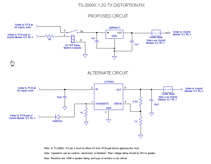
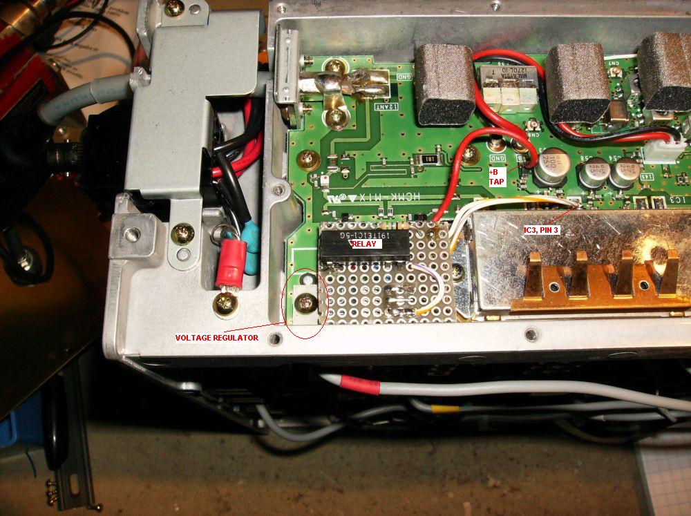
I decided that I would not miss the VHF contest a couple of weeks later, so I went ahead and opened up the hood on the TS-2KX to try to better assess the problem. I probed the Vbb DC biases on pin 3 of the two modules when in Transmit and saw what follows:
The Mitsubishi specsheets specify a bias of +8Vdc and +9Vdc, with an absolute maximum value of +9Vdc and +10Vdc respectively. So the modules were clearly under-biased and the values corresponded to the problem description I had read on the internet, but was it really the source of problem? Next,
I decided to probe the RF signal to hear from where the distortion
originated. I used a 20:1 resistive RF probe, fed its signal into a
60dB power attenuator and
on to a receiver capable of tuning to 1296MHz. I
terminated the antenna
connection into a dummy load. I then keyed up the
1296 transmitter and probed the RF lines at the
input of IC2, between IC2 and IC3 and at the output of IC3. I quickly
determined that IC3, the P.A. hybrid, was the source of severe
distortion. Disconnecting
IC3, pin 3 from its PCB connection is
a rather simple thing to perform; it is just a matter of carefully
lifting off the pin while heating up with a soldering iron. So I just
did that. I then set the voltage on an
external power supply to
+8Vdc and connected it up to pin 3. I saw a constant 300mA of
current flowing. The absolute maximum current specified is 500mA so
everything looked nominal. I then transmitted again and YES!!! Clean SSB signal. I then knew
how to fix it.
The following were the facts
that I had to deal with in my implementation of a fix:
Since IC2, the driver module, did not manifest the same problem, I decided not to touch it. When ain't broken, don't fix it... Enjoy!
|