|

|
|
My 10
GHz Narrow-Band Transverter System
|
Taking
a cheaper and longer road...to 3 cm
microwaving!
|
|
By: Bertrand Zauhar, VE2ZAZ / VA2IW
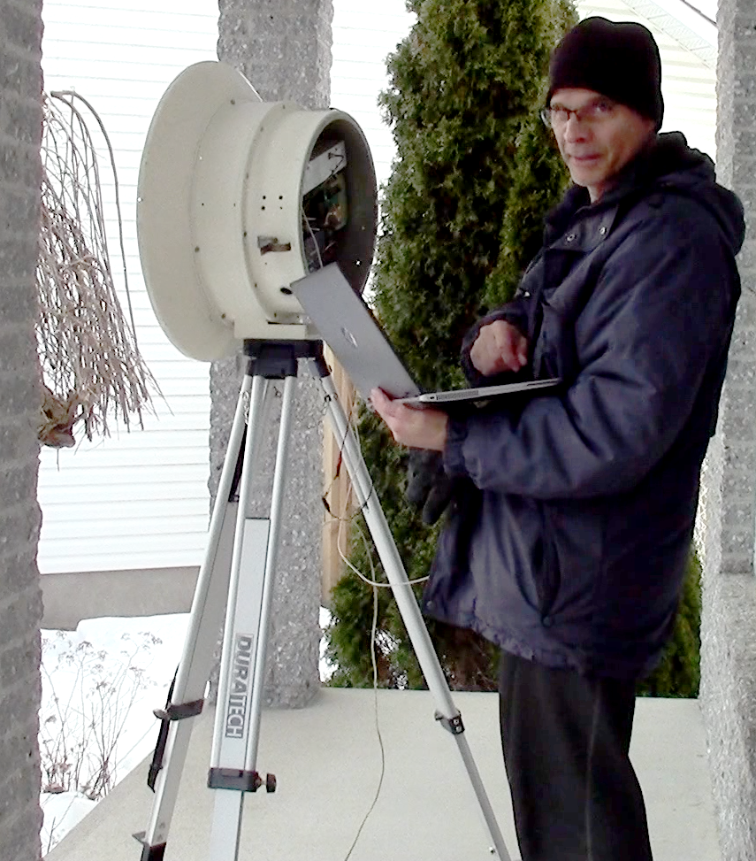
This was a winter of 2024 project,
and a commitment to myself: Put together a 10
GHz transverter and dish system, and spend as
little as possible in the process! This
meant re-use what I had on hand,
design and/or assemble as much as
possible. In the end I got a good
performance system, and had a lot of
fun putting it together.
Updated -
2024/08/06: On the
Sequencer board, lowered the
value of the current setting
input resistors on the PhotoMOS
relays, from 4.7K to 2K. This
guarantees proper relay
operation at hotter ambient
temperature (in the sun!).
When reading through this web page, please
put the following into perspective:
- I already owned the
required microwave test instruments to
properly test the project,
- I had Surface-Mounted
Device soldering skills and tools,
- I already had many of the
required components and hardware,
- RF design is in my skill
set, and had no fear of tackling this
project.
Simply
put, this project is not for the
standalone beginner. A lot of it is
custom-designed for this particular
system, and may not work on other setups.
However, I share the following in hope
that others can re-use some of these
concepts and approaches on their own
setup.
| This
web page
provides some
details of the
final system.
However, if you
are interested
in knowing much
more on the project,
follow the
design steps I
took and the
measurements I
made, you MUST
watch my series
of 25 (yes!)
short progress
report videos.
The YouTube
playlist is
accessible by
clicking on
the thumbnail
to the right.
|
|
These
were the objectives I set early on
in the project:
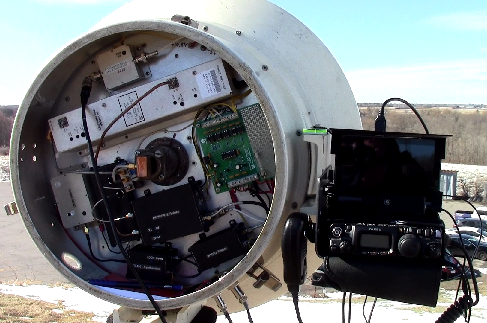
- Use
the 10GHz dish I already owned
and fit everything in the rear
compartment,
- Design
and/or assemble as much as
possible,
- Shoot
for at least 1Watt of transmit
power (2-3 W would be great),
- Try
to 3D-print the various
enclosures. EM shielding
practical?
- Use
my existing FT-817ND radio as
the 144 MHZ IF radio (note that
I eventually switched to an
IC-705 for the IF),
- Spend
AS LITTLE AS POSSIBLE! Will I
use the system often?
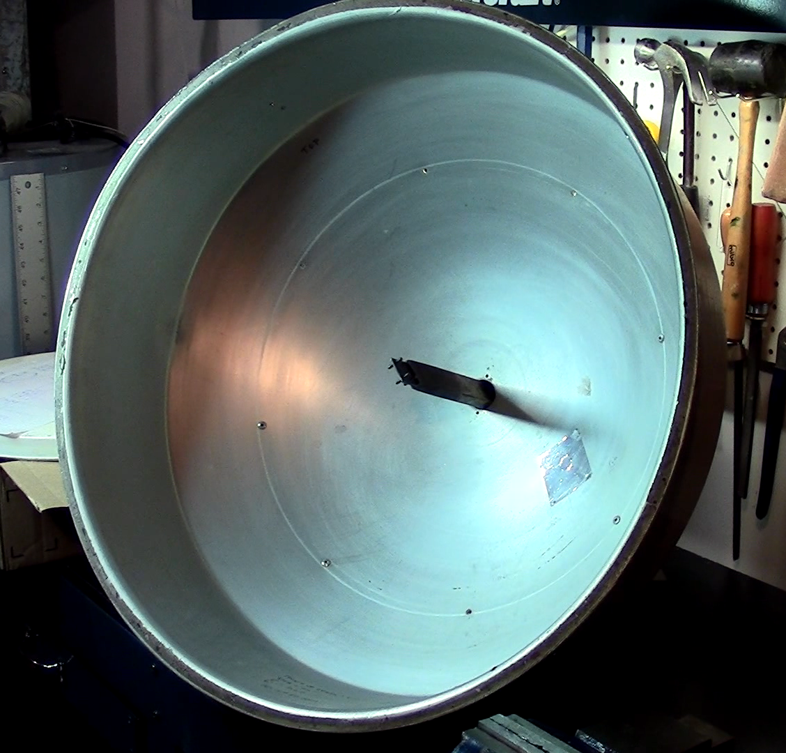
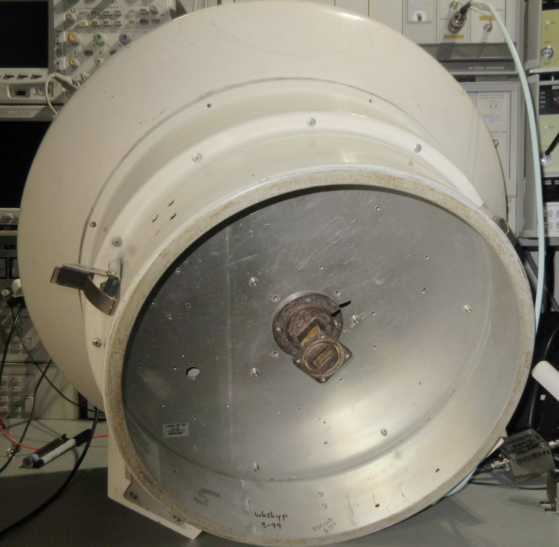
The Parabolic Dish
I bought it used at a hamfest, paid
$20 USD including the feed. It is a
22-inch (57 cm) diameter prime focus
dish with the following
characteristics:
- f/D ratio: 0.27
(a deep dish)
- Calculated gain:
~34dB @ 10.368 GHz
- Had a side shield
(ended up cutting it off later),
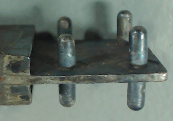
- Included a 10 GHz
dual-dipole feed, offering linear
polarization,
- Good for deep dish,
- Built on a WR-90
waveguide,
- Has a standard
UG-39/U Flange,
- Cut to focal length
f = 6 inch distance from the
bottom of dish,
- Optimal for my
dish?
- There is a rear
compartment with cover, very
convenient!
- Has two welded on
mounting plates, good for tripod
mount and IF radio side shelf
addition,
- Is all aluminum,
however still somewhat heavy for
hand carried expeditions.
See
video #1 for more detail: https://youtu.be/cHVOxPAIHcA
|
 |
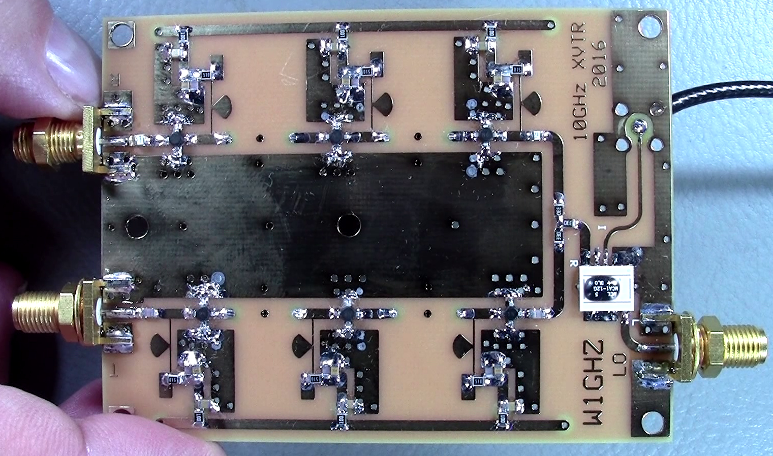
Mail
Order From W1GHZ
The following components were ordered
from Paul Wade - W1GHZ's website.
Prices are very reasonable,
and it saved me from having to
re-design these blocks and having to
separately order some of the key
components I did not already had on
hand.
- Transverter PCB,
- Tripler PCB,
- 10x NLB-310 10 GHz
MMIC Amps, used on the above PCBs,
- 2x MCA1-12G Mixers
(one spare…), used on the
transverter PCB.
The transverter and LO
Tripler designs are well documented on
Paul's website. See http://www.w1ghz.org/xvtr/transverter.htm,
and also browse other pages of his
website, as all the 10 GHz stuff is
not regrouped on the same page.
See video #8 for more
detail: https://youtu.be/Fq8jSmYnjW8
|
|
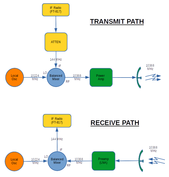
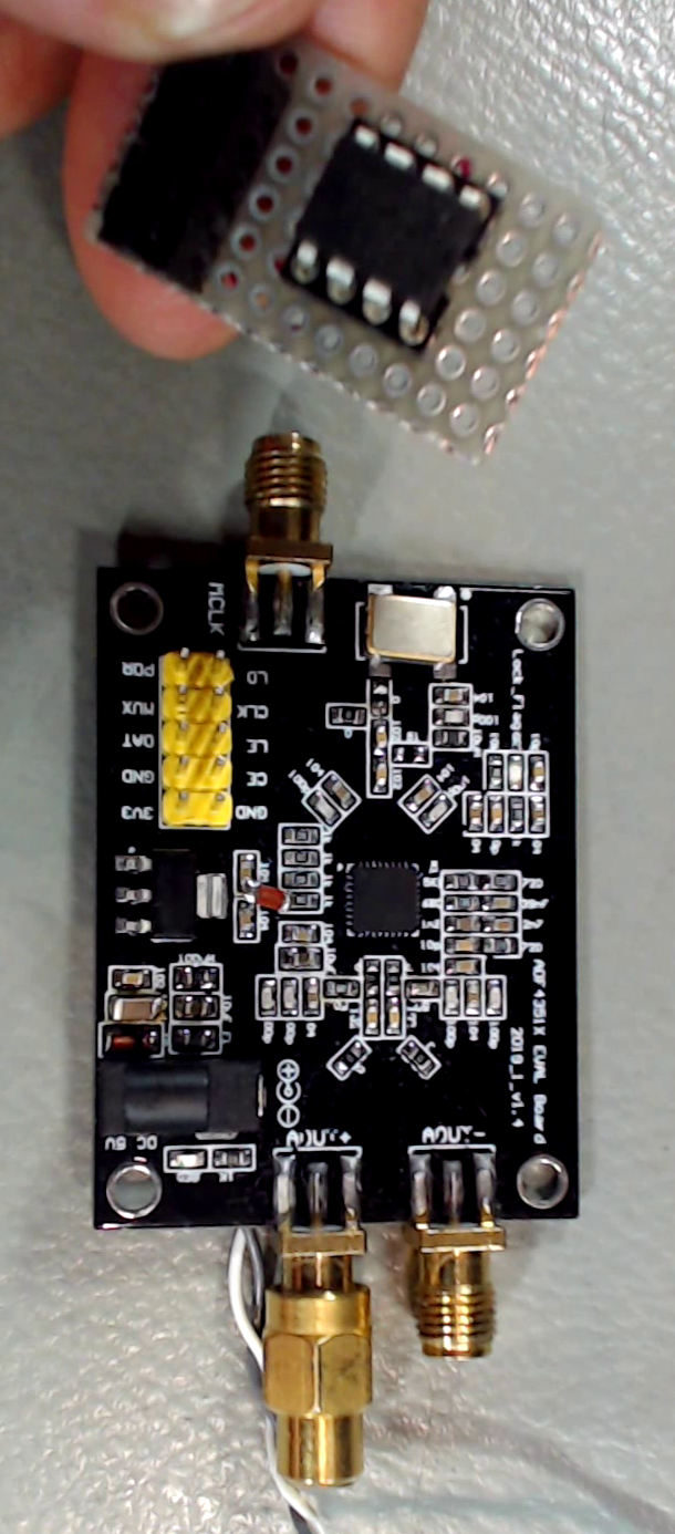
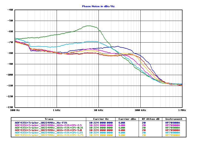
Local
Oscillator (LO) Design
It is based on a Chinese-made
ADF4351 Board, which sells for
around $25 USD on AliExpress,
- Covers
34 – 4400 MHz, with Max.
output of about +3 dBm,
- Can
accept a 10 MHz input
reference,
- Needs
programming at power up. I custom-designed a
PIC12F683 micro-controller
firmware that:
- Sets
output to 3408 MHz,
- Sets
Maximum output power.
- Sets
the PLL loop current to
minimize output spur
generation.
- ADF4351 board
also requires a few physical
mods to improve phase noise
performance
- Disable
on-board oscillator,
- Add
bulk capacitive filtering on
+5V rail.
- Add
pull-up resistor to force
output to be always on.
The firmware source
file was written
in XC8 C
language, for a PIC12F684
micro-controller target. It
can be compiled in the MPLABX
IDE.
See videos #6 and #12
for more detail:
https://youtu.be/DzZl1HtuDBA
https://youtu.be/3q-5-Ht0lL4
|
|
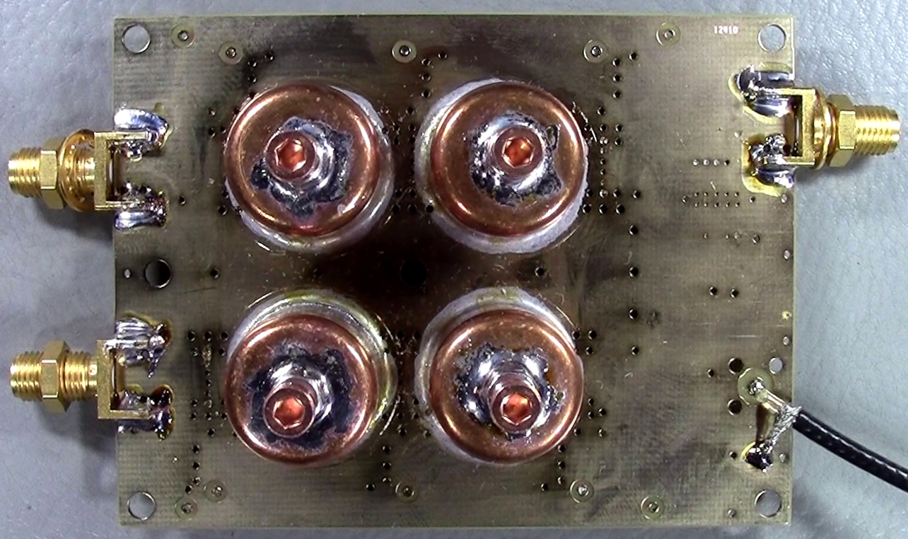
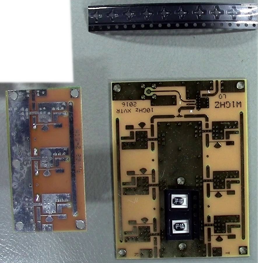
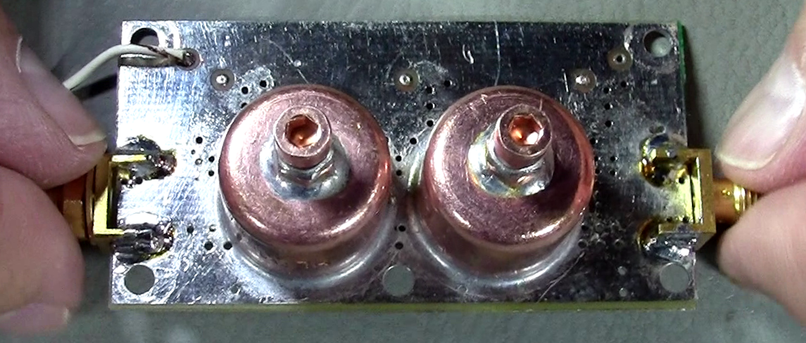
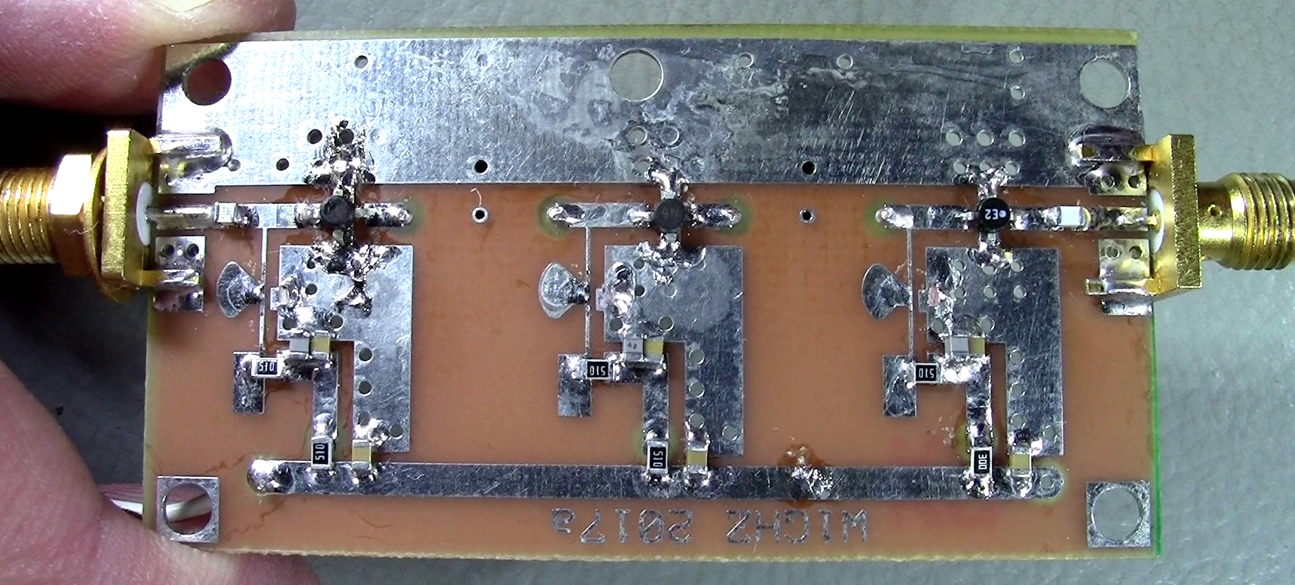
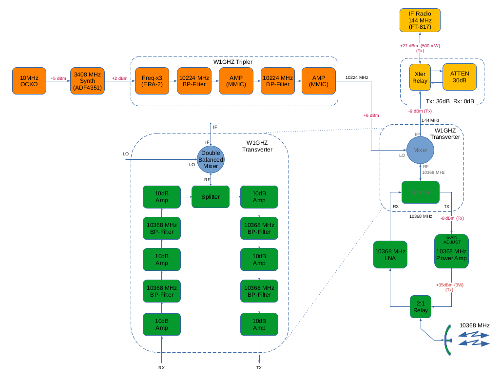
LO
Tripler
It is based on the W1GHZ
Tripler board.
- Has three MMIC
amplifier stages, the first one
being saturated to produce
harmonics,
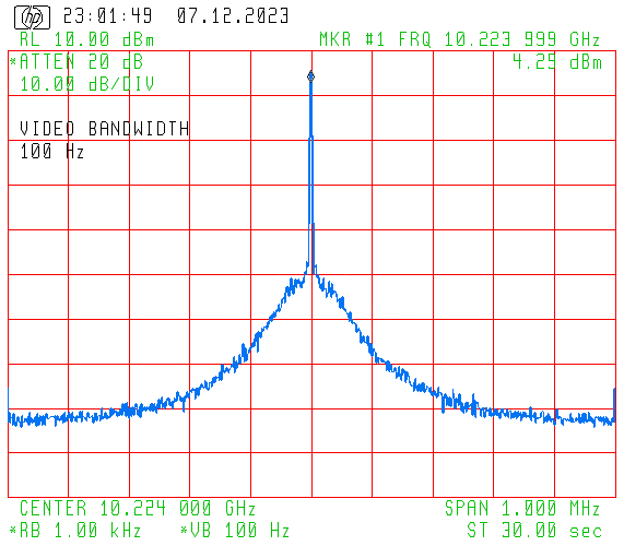
- The two 10GHz Pipe
Cap Filters are tuned to 10224 MHz
LO frequency,
- Produces a +6 dBm (4
mW) output power, enough to drive
the Double-Balanced Mixer on the
transverter board.
|
|
|
|
10GHz
Transverter
It is based on the W1GHZ Transverter
board.
- Has three amplifier
stages on both Rx and Tx paths.
Amplification is kept linear to
reduce harmonics generation,
- Uses:
- An on-board
resistive splitter/combiner,
- A Mini-Circuits
MCA1-12G Mixer,
- Four 10GHz Pipe Cap
Filters tuned to LO frequency,
- Independent +8V
supply rails for Rx and Tx
strips,
- Produces a 0 dBm (1
mW) output power,
somewhat lower than ideal, however
is enough to drive the Alcatel
Power Amplifier.
See video #10 for more
detail: https://youtu.be/oA-fHLZmvXY
|
|
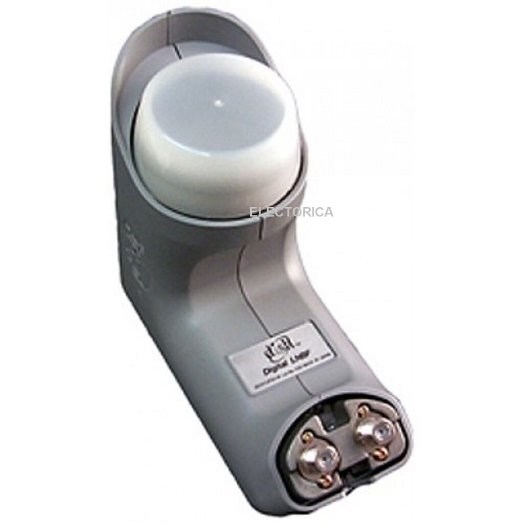
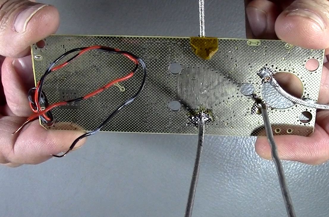
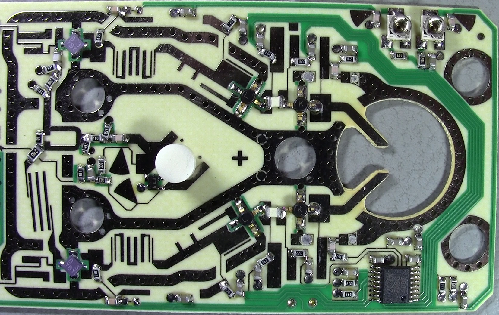
10GHz
Low Noise Amplifier (Rx Preamp)
It is a recovered Bell-ExpressVu
(Dish-Network brand) DSS offset dish
LNB (see picture to the right),
- Natively covers the
Ku band, 12-13 GHz. Offers two
usable broadband preamplifier
strips (cross polarization
satellite coverage), which work
great at 10 GHz.
- Uses a low noise
NEC Hetero-Junction FET
transistor front-end,
- Offers a 20+ dB
Gain and a 0.35 dB NF!,
- Mods performed:
- Disconnected the
downstream band-pass filter and
mixer.
- Disabled the
on-board Local Oscillator.
- Kept the existing
supply and FET bias circuits.
Fed +8 VDC into the +5 V linear
regulator,
- Cut off the
existing input probes,
- Interfacing the
input and output coaxial cables
was the challenge. Made
perpendicular-to-board-surface
connections with conformable
coaxial cable, from the PCB
bottom side, and through a tiny
hole aligned with input and
output copper tracks.
Conformable cable shield is
soldered to bottom side copper
plane.
- Careful! Thin,
brittle PCB material and copper
foil is used on the LNB PCB. Avoid
excessive mechanical stress, and
do not overheat.
See video #13 for more
detail: https://youtu.be/EfDosDKckak
|
|
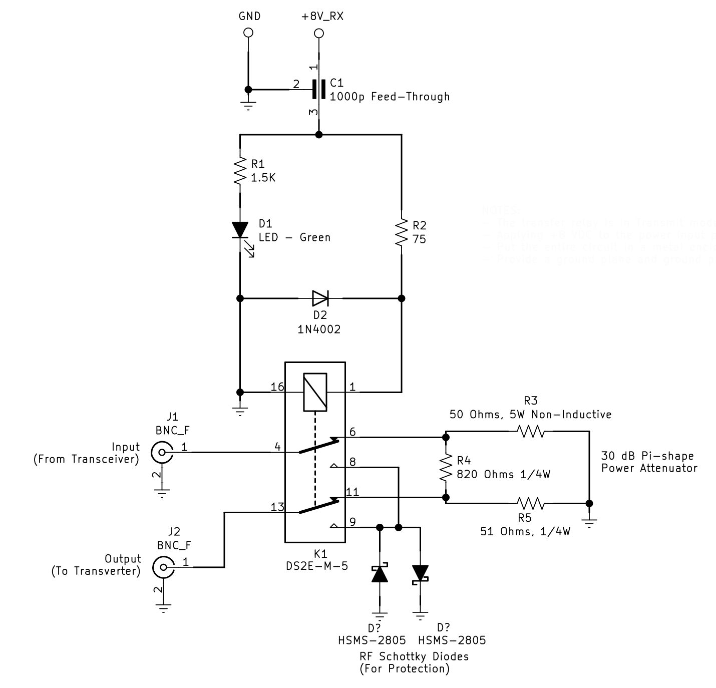
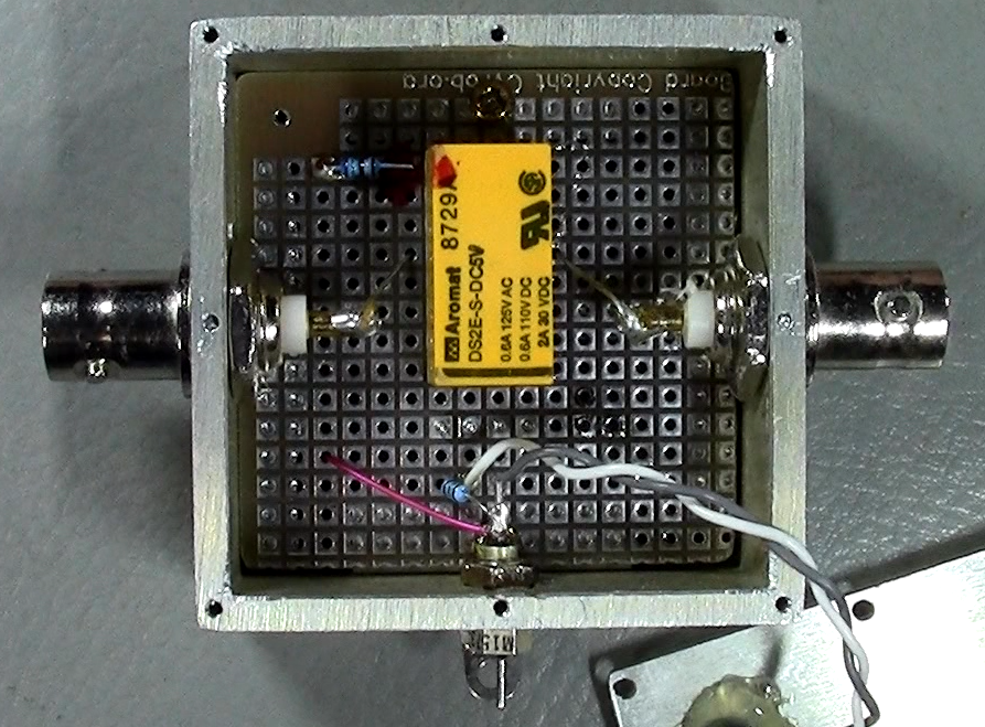
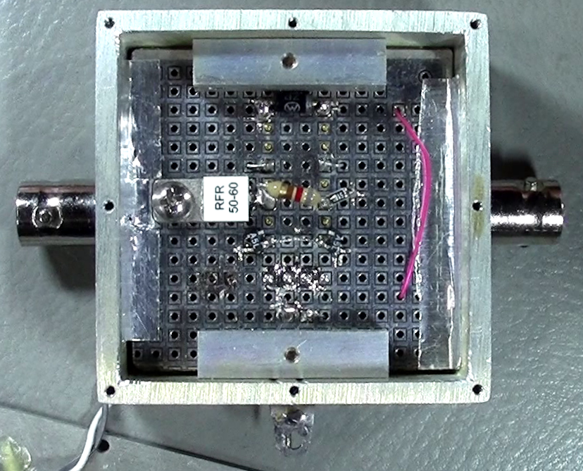
144MHz
IF Transfer relay and Attenuator
- Is hand-made on
universal PCB,
- Offers a 30 dB
Pi-shape Attenuator in Tx and a
straight through path in Rx,
- Defaults to
attenuated path (Tx) to protect
the transverter mixer,
- Uses a 50-Ohm power
resistor, purchased on AliExpress,
- Uses a standard 3-Amp
DPDT power relay,
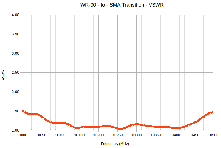
- The measured VSWR is
1.4:1 Good enough for ZAZ!
|
|
|
|
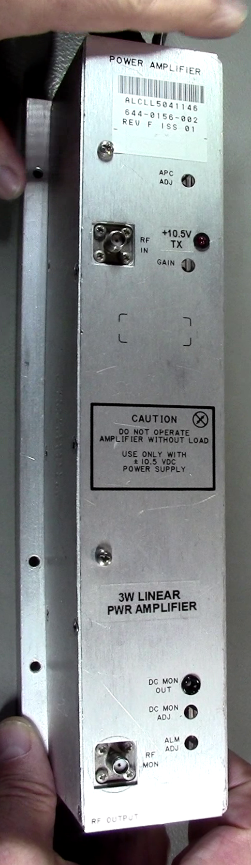
10 GHz
Power Amplifier
The PA was recovered from an
Alcatel MDR-6000 point-to-point
microwave system.
- RF Power: -5 dBm in,
3+ Watts out,
- High input
sensitivity saves from adding an
extra boosting stage between the
Transverter and the PA,
- It is a Class A
amplifier, so is DC power hungry
- Amplifier
is 13% efficient (best case!),
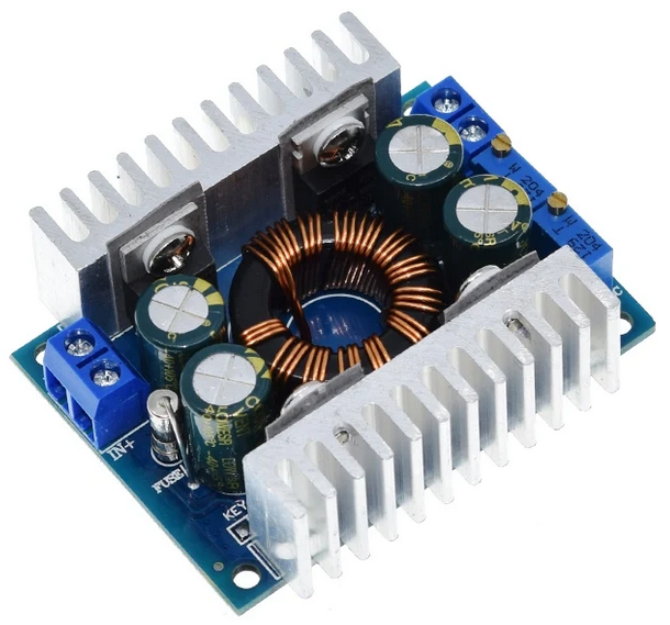
- +10.5V @ 2.2 Amps,
- I
used a Buck-Boost converter
for the +10.5 V supply, with
added input and output low
pass LC filtering,
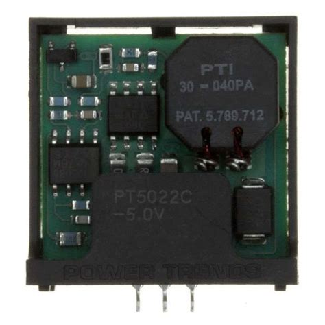
- -5V @ 10 mA,
- I
used a +5 V to -5 V
converter, with added
input and output low pass
LC filtering.
- Has a thick bottom
cooling plate, so no heat sinking
is required for our intermittent
ham operation,
- Measures 8 inches
long, and is rather heavy at 3.5
lbs,
|
|
|
|
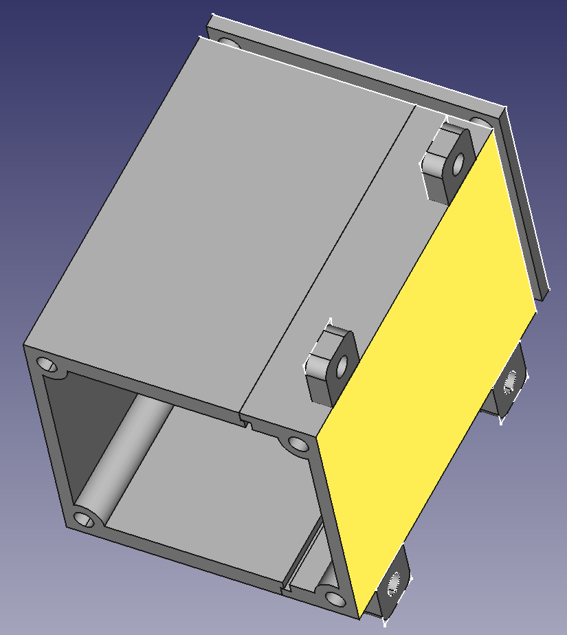
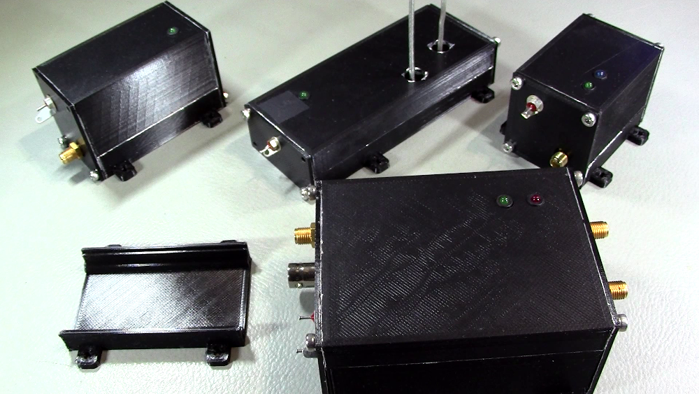
3D-Printed
Enclosures
Various parts of the system were
contained in custom-designed
enclosures designed in FreeCAD.
- Printed in PLA
plastic. Took 2 to 3 hours for
each piece of an enclosure,
- Inside walls were
lined with self-sticking aluminum
duct tape. The tape extended to
the outside of the bottom surface,
- The enclosures have
an inside lip that squeezes the
board between the top and bottom
parts,
- All holes were
drilled afterwards,
- Feed-through
capacitors were added for
precaution on the DC supplies,
- Power on LEDs were
added afterwards,
- 3mm Hex head screws
hold the end plates.
|
|
|
|
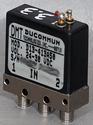
Coaxial
SMA Relay
- Used a standard 1:2
microwave SMA coaxial relay,
- Good for several
Watts of RF when not
hot-switched,
- The 24 VDC version of
these relays is much cheaper than
the equivalent 12V version,
- However a 24V source
is required,
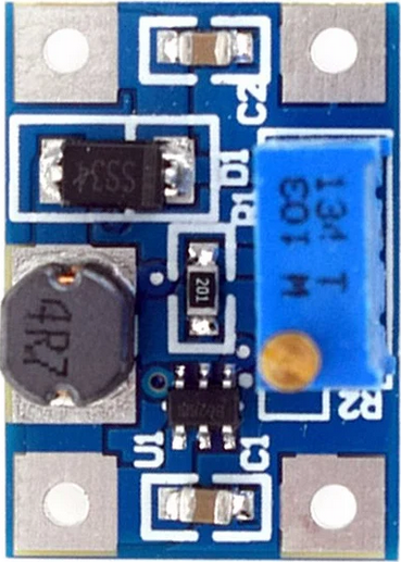
- Used a small
Adjustable DC-DC Boost
converter,
- Costs less than 1$,
- Is a switching
supply: Noisy, however not too
critical since only activated in
Tx. I added some extra
capacitive filtering on input,
- 8-14V in, adjust to
20-26V out, depending on relay
requirement,
- A 20V output is
fine for 24V relays. Reduces
coil current,
- Also added a
back-EMF protection diode on
converter output,
- Mounted it to the
relay using a small screw and
some double-sided sticky tape.
|
|
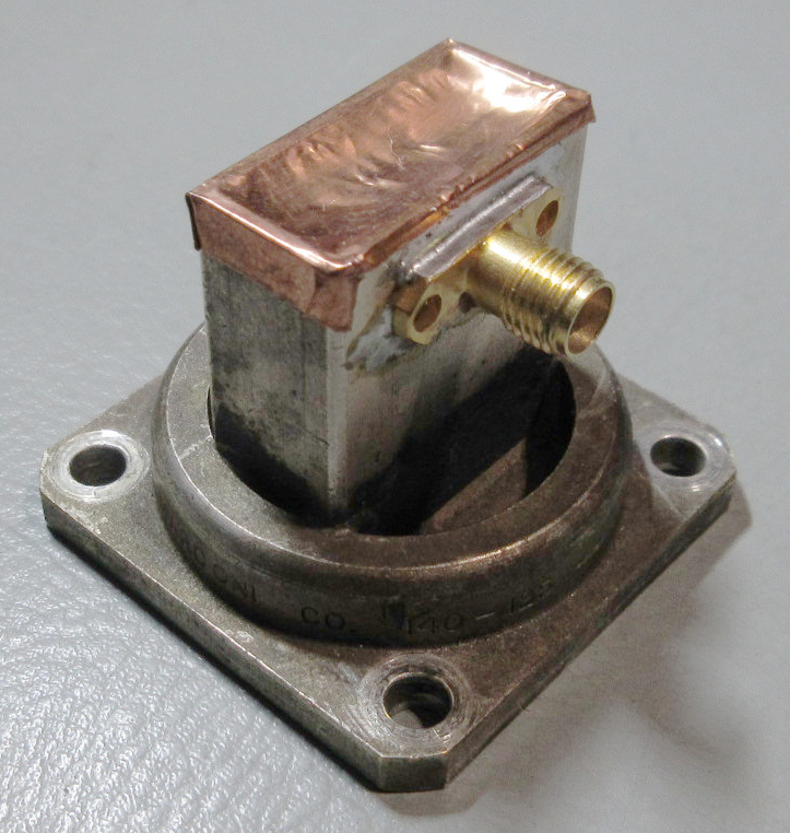
Waveguide-to-Coaxial
SMA Transition
I made a WR-90 waveguide to SMA
transition using a surplus waveguide
piece with existing UG-39/U flange at
one end.
- I followed W1GHZ’s
recipe (QST magazine article,
Nov/Dec 2006,
- I used a SMA
connector/probe I already had, cut
it to proper length, drilled the
wall and and positioned the probe
as per the article. Note that a
lot of heat is required to solder
on a silver-plated brass
waveguide! So I pre-heated the
unit on a heating plate prior to
soldering the connector.
- Using a signal
generator and directional coupler,
I tuned the transition by pressing
down on the copper foil rear wall
(see photo of VSWR once
installed on dish).
See videos #3 and #4 for
more detail:
https://youtu.be/rtLG-l7ExIQ
https://youtu.be/LJnOWWF39iE |
|
Everything
else
Over the 40+ years of doing ham radio, I have
accumulated a lot of electronic components,
hardware, cables, wires, etc. Obviously, for
anyone building such system, the cost of these
elements would have to be taken into account,
something I did not do.
Power Distribution Diagram
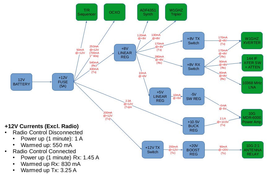 It is inspired
from “FT-817 Transverter Sequencer”
paper by VK4CP / VK4GHZ, and re-designed
by me for this application,
It is inspired
from “FT-817 Transverter Sequencer”
paper by VK4CP / VK4GHZ, and re-designed
by me for this application,
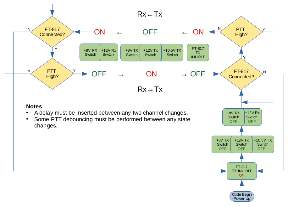
- Uses a
PIC16F1824 micro-controller,
firmware written in Microchip C
language.
- Fixed 40
ms delay between each channel,
modifiable by recompile.
- Uses
versatile AQV212 PhotoMOS Solid
State Relays for the outputs.
- Detects
the presence of the FT-817 (or
IC-705), senses PTT, inhibits IF Tx
power until Tx sequence is
completed.
- Provides
+8V_Tx, +8V_Rx, +12V_Tx, +12V_Rx,
+5V.
- Controls
the +10.5V DC-DC converter (for the
Alcatel Power Amp.)
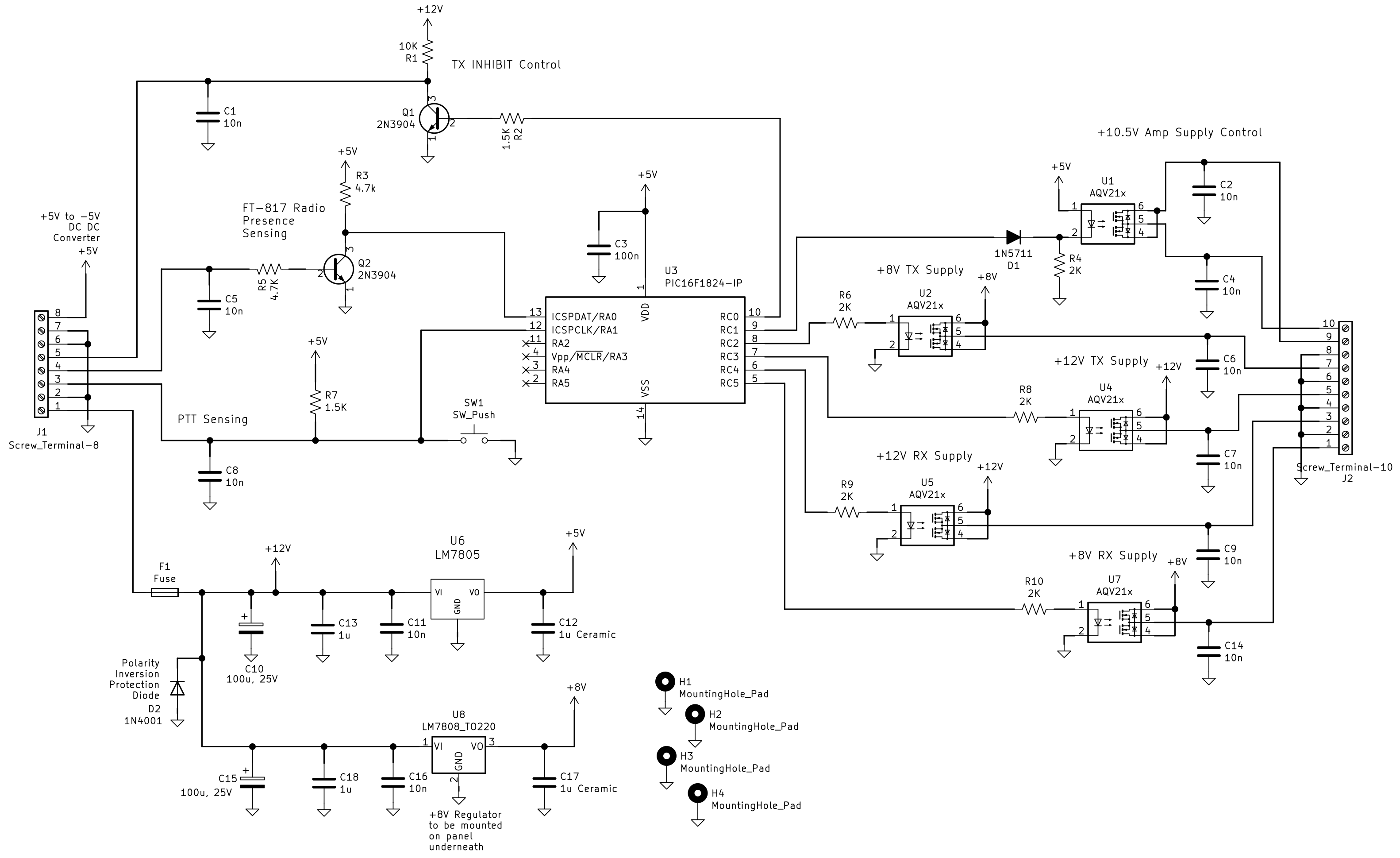
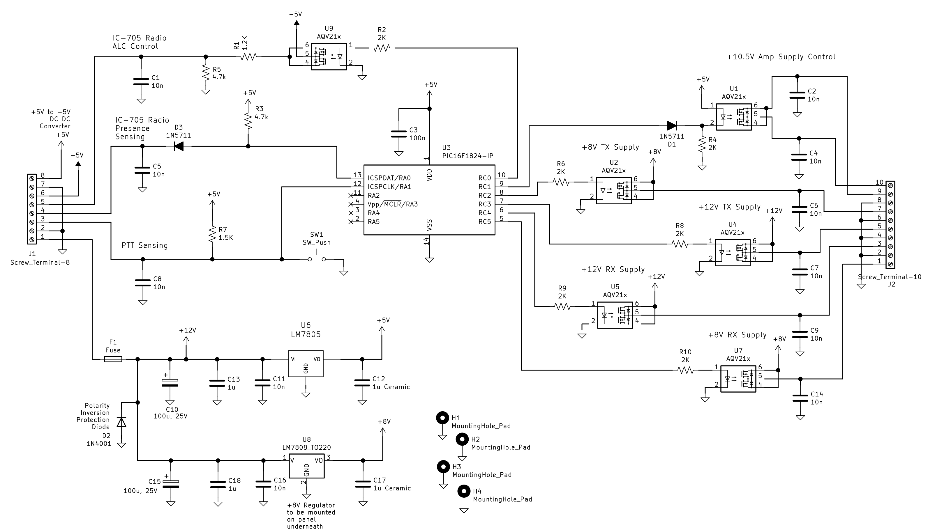
I produced two
versions of the design for different IF
radios, the Yaesu FT-817/818 and the Icom
IC-705. The main difference resides in how
the Tx RF power is inhibited until
everything is switched. On the FT-817
version, the TX Inhibit input pin is used.
On the IC-705 version, the radio's ALC input
voltage is controlled instead.
Circuit
Schematic for FT-817
Circuit
Schematic for IC-705
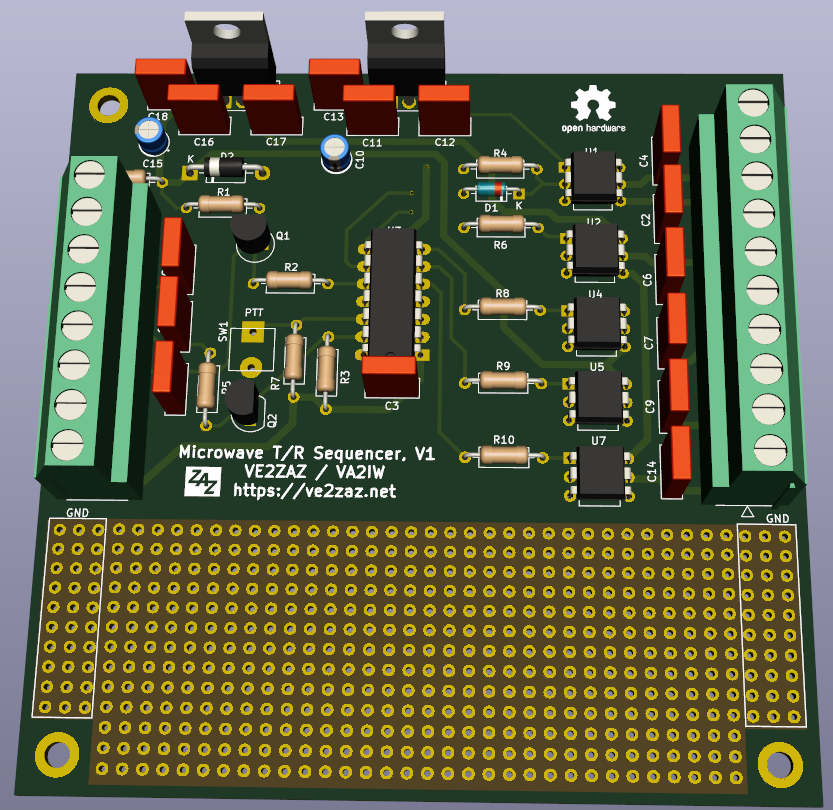
Sequencer
PCB
- Made 100x100mm in
size, outline and features meet
usual PCB manufacturer low cost
deals,
- Includes a
prototyping area, allowing for
expansion or feature addition,
- The +8V regulator
must have proper heat sinking, as
that voltage rail could provide up
to 800mA.
- Designed in KiCAD.
|
|
Firmware
Flow Diagram
Firmware Source
File
Here is the firmware source code,
written in Microchip XC8 C language, for a
PIC16F1824 micro-controller target. It can
be compiled in the MPLABX IDE.
See
video # 20 for more detail:
https://youtu.be/D3IxH2UfIGM
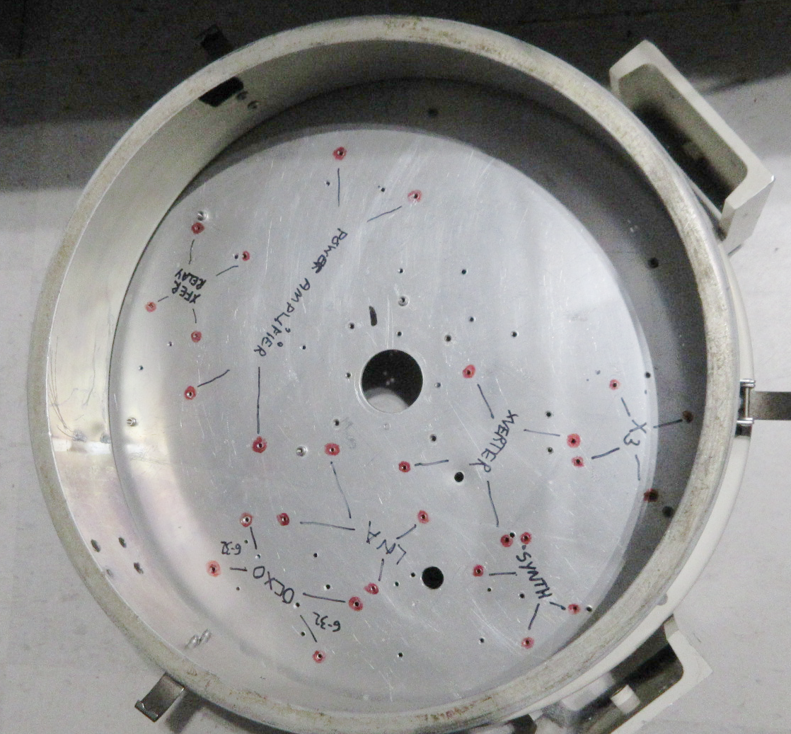
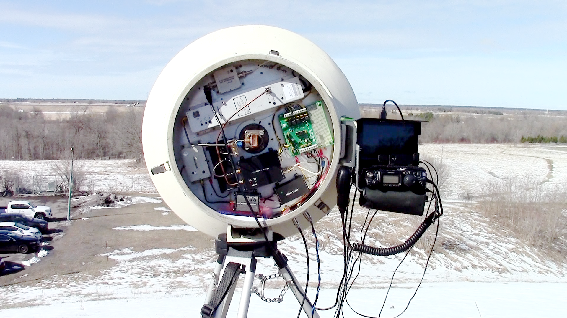
Floor
space planning is a compromise
exercise.
- Optimized for the
shortest RF links,
- Marked, drilled and
threaded all module mounting
holes,
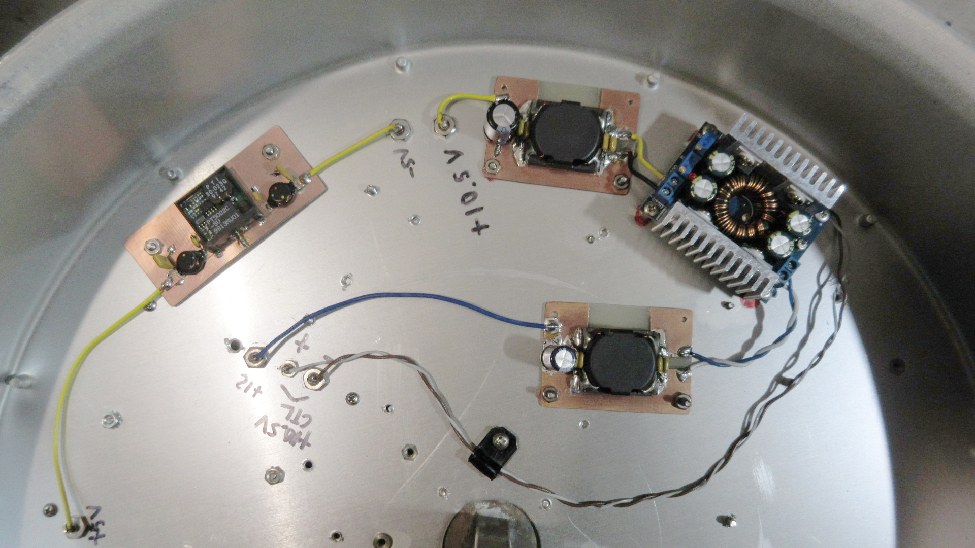
- Segregated the
switching converters,
- Available RF-tight
space between dish and rear
compartment. Used it for the PA
switching converters,
- Installed
Feed-through capacitors between
compartments.
- Added low-pass LC
filtering on inputs and outputs
to reduce switching noise.
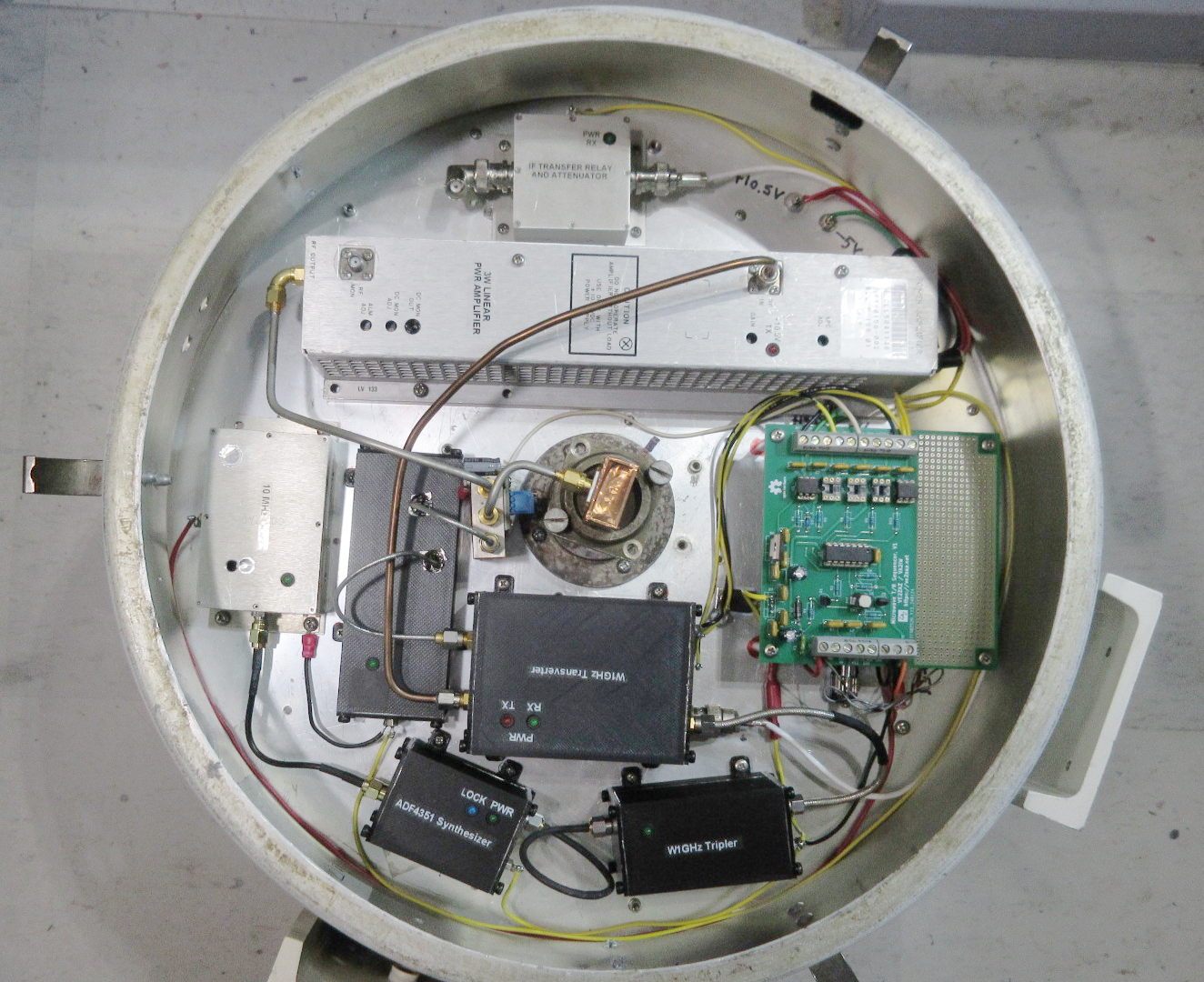
- Installed all
modules, sequencer board and power
terminal (under sequencer),
- Wired up the various
power lines: Always on, Tx and Rx,
- Installed the proper
coaxial lines:
- Regular RG-type
coax for IF and 10 MHz, BNC
connectors,
- “Conformable” PTFE
coaxial or Semi-Rigid UT-141
PTFE coaxial for 3.4 GHz and 10
GHz, all with pre-installed SMA
connectors.
See videos #21 and #22
for more detail:
https://youtu.be/dmCWcGQ1GIM
https://youtu.be/Hf6M1rQftpg
|
|
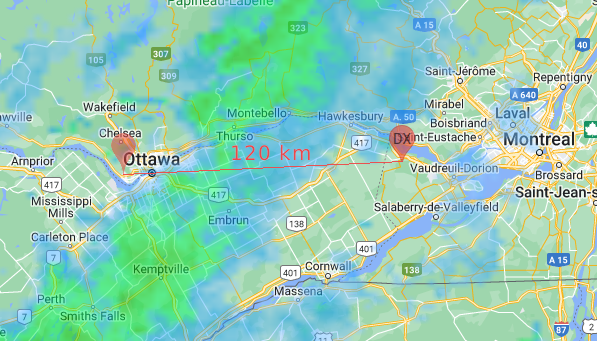
The
first trials were receive tests
of the VE2TWO beacon, located in
grid square FN25uk, on the top
of Mont Rigaud, some 120 Km away
from my front porch! And it
worked repeatedly! Hear the
result here:
https://youtu.be/j7PxdoeTBKw
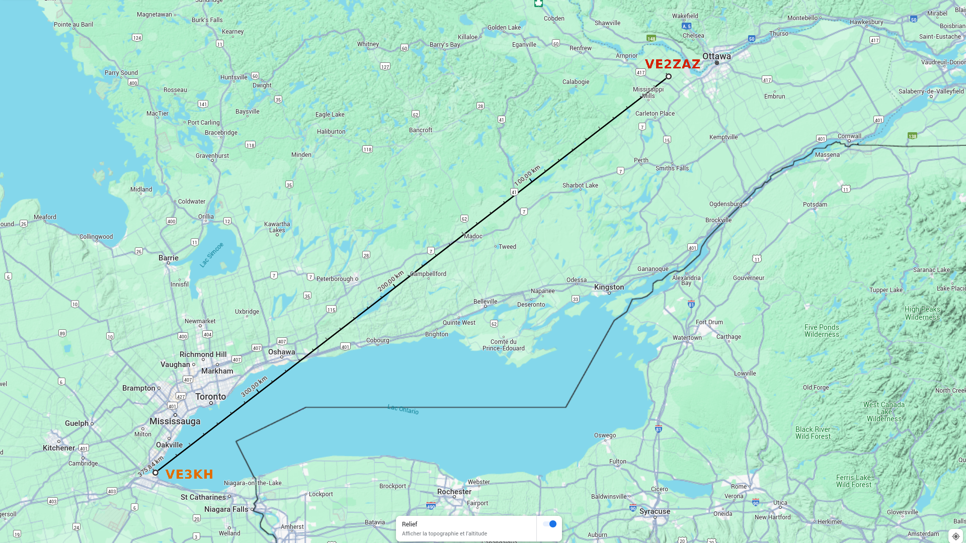
My first 10 GHz two-way QSOs
took place on April 6th, 2024,
from grid square FN15xi. Grid
square FN03 was reached three
times, with a maximum QSO
distance of 376 Km between VE3KH
and myself. Hear and see the
result here:
https://youtu.be/Mf-WBhdVY7A
Another QSO with VE3KH took
place in June 2024, this time
using rain-scatter propagation.
Hear
the QSO here:
https://youtu.be/uAOAHR4Jhyc
|
|
All in all, I am very pleased with system
performance. I spent around $400 on that
system, which is much less compared to
buying off-the-shelf modules. Of course,
there are improvement that could be made.
However, I will make several more QSOs
before changing anything. This will allow
me to compare the results with other hams' co-located 10
GHz systems, and assess areas of
improvements.
|
|