|
|
By: Bertrand Zauhar, VE2ZAZ / VA2IW Last updated: 29/08/2023 I enjoy my ICOM
IC-7300 HF/6m SDR transceiver. It offers the performance and features
that I need...except for one thing: more than
one antenna port! I find this to be a
serious limitation, which forces me
to add an external coaxial antenna
switch. Fine, you say? Well, do you
participate in multi-band HF
contests? Having to manually select
a different antenna every time I
change bands is annoying and leads
to having a wrong antenna selected.
It has happened to me more than once
to transmit into the wrong antenna,
and not knowing why I am not being
heard! Another feature I wished I
had was the ability to select a
different antenna for receive, and
then to automatically switch between
the two antennas between transmit
and receive. There had to be a way
to automate antenna selection. And I
took care of that!
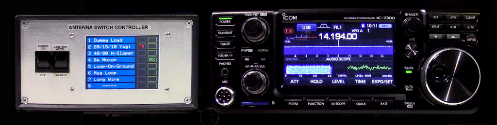
Here is the project I describe in this page: A smarter control box for a remote antenna switch that manages antenna selection as a function of frequency, and does much more. It:
 At a
recent hamfest, I purchased a used
Ameritron RCS-10 8-port remote
antenna switch (see image to the
right) for $45, a very good deal.
For me this is an appropriate
antenna selection solution,
considering that I have six HF or
6m antennas to choose from (some
of them for receive-only
operation). The RCS-10
switch
is made of two parts, the outdoor
remote switching unit (above in
picture) and the in-shack control
box (below). The latter operates
in a manual fashion: a rotating
knob sends voltages to the remote
switch to select the desired
antenna out of the 8 ports.
Simple...and dumb! Ameritron sell
a smarter control box for their
remote switches, the RCS-12C
Automatic Antenna Switch
Controller. But it goes for $300 +
shipping. It is just a control
box! At a
recent hamfest, I purchased a used
Ameritron RCS-10 8-port remote
antenna switch (see image to the
right) for $45, a very good deal.
For me this is an appropriate
antenna selection solution,
considering that I have six HF or
6m antennas to choose from (some
of them for receive-only
operation). The RCS-10
switch
is made of two parts, the outdoor
remote switching unit (above in
picture) and the in-shack control
box (below). The latter operates
in a manual fashion: a rotating
knob sends voltages to the remote
switch to select the desired
antenna out of the 8 ports.
Simple...and dumb! Ameritron sell
a smarter control box for their
remote switches, the RCS-12C
Automatic Antenna Switch
Controller. But it goes for $300 +
shipping. It is just a control
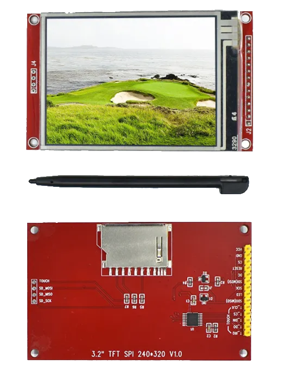
box!Other manufacturers like DX Engineering, MicroHAM, SPID, RAAS and HAMPlus offer antenna switching solutions with a varying degree of smartness, but putting together one such multi-port smart switching system will end up costing several hundred dollars, and some will even cost more than a thousand dollars. I cannot accept spending so much money just on antenna switching. Instead, I can re-use my RCS-10 remote antenna switch, and design my own controller box for way less than a $100, and it will have all the features that I need, including a touch screen! In order for the controller to select the right antenna based operating frequency, a data link to the radio is needed. The IC-7300, like many ICOM HF transceivers (IC-706, 718, 735, 746, 756, 7000, 7610, 7851, just to name a few), is equipped with a physical "Remote" jack conveying the CI-V control protocol. The idea is to read back the current operating frequency from the radio, and then select the antenna accordingly. It would be neat to be able to select two different antennas, one for receive, one for transmit. For Rx-Tx antenna switch-over, a Push-To-Talk RCA jack is available on the rear of the '7300 to control an external power amplifier. That line can be sensed by the switch controller for fast antenna transfers. With my RCS-10 switch, the required hookups to the IC-7300 and my design skills, I can put together a nice solution! And I can throw in enough flexibility so that it accommodates many different models of remote antenna switches having a various numbers of antenna ports. Now let's go more technical!
The best way to understand what this project offers is by first consulting the Circuit Schematic of the board below (click on schematic to enlarge): 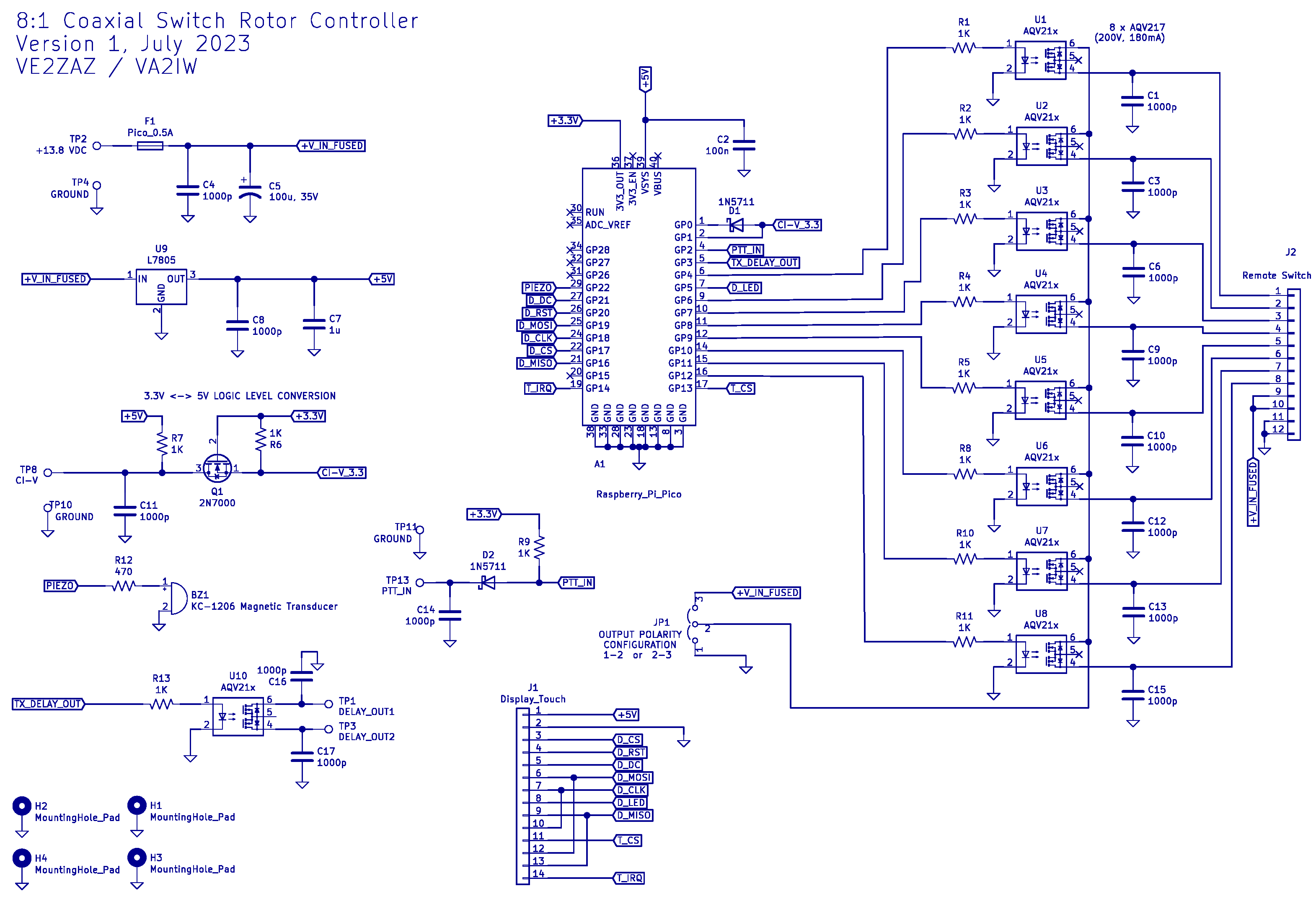
The circuit is rather
straightforward. Here are its main
features.
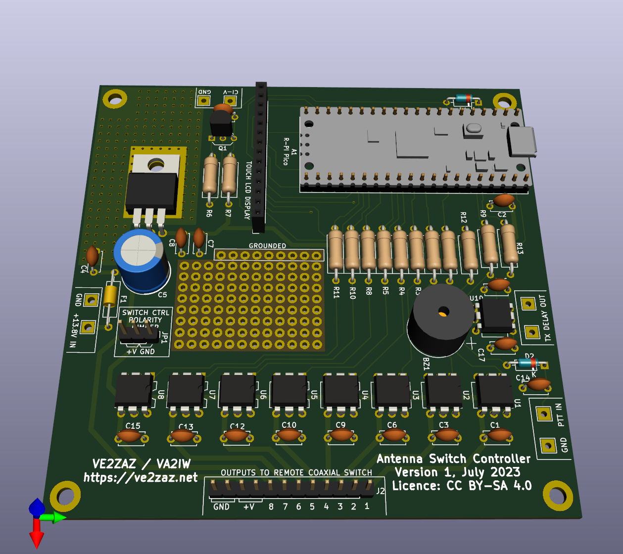
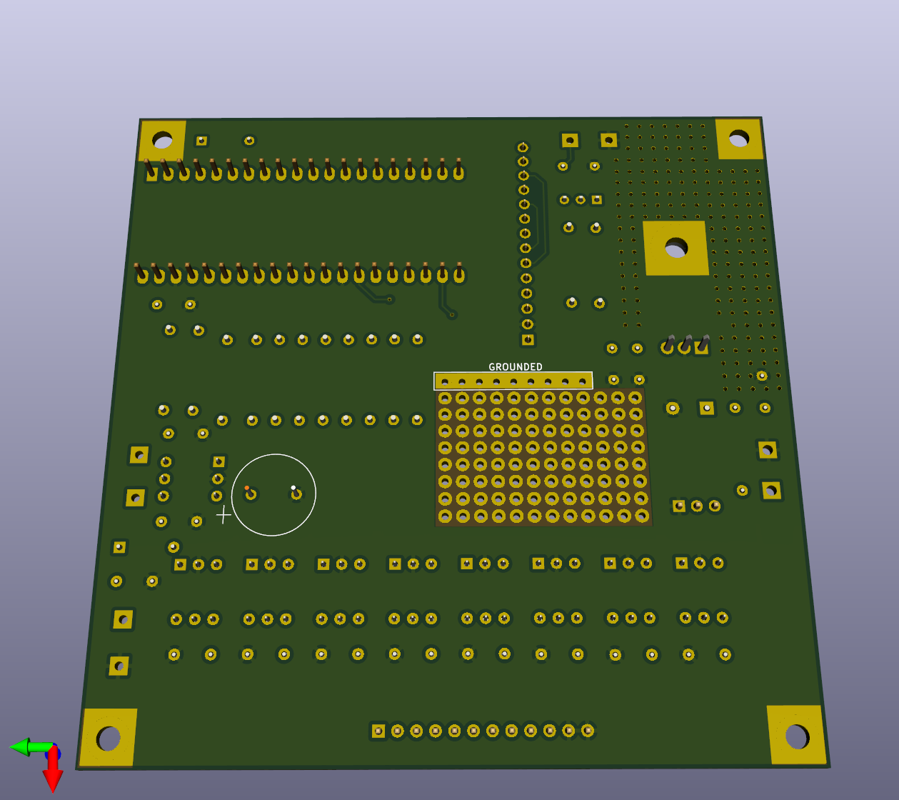
The Printed Circuit Board is a double-sided design, 100 x 100 mm in size, with plated-through holes, solder resist and silkscreen (marking) on both sides. All components are of through hole mounting type. The PCB features a small prototyping area in the center, allowing for hardware additions if new features are required. In the zip file, I provide the KiCAD design files, the gerber and drill files to anyone who would like to order it. Such PCB can be ordered for around $20 per lot of 5 PCBs. One simply provides the gerber files and the drill files to the manufacturer. I normally order from JLCPCB, but other major manufacturers will produce the same quality. In your order, select 0.062" (1,6 mm) thickness FR-4 glass-epoxy material, the standard.
The following is a list of all required components and sub-modules to put together this project. Note that there are components whose quantity can vary based on the number of remote antenna switch control lines required. These components are identified with a asterisk (*) in the Qnty column. See the ASSEMBLY section for more detail. In general, component selection is not critical on this project. As a result, one can order all required components from known local suppliers (Digikey, Mouser, Element-14, etc.), or order from Asian online suppliers like AliExpress, Banggood, DealExtreme, etc. The latter approach will yield a much lower total cost. On-Board Components
Additional Components and Hardware
The board is not particularly difficult to assemble by hand. The components are mounted and soldered onto the PCB in a through-hole fashion. A small tip soldering iron and some solder wire is appropriate for the job. A decision on the number of output lines to populate must be made while assembling the board. The number of control lines on the target remote antenna switch will dictate how many, as a minimum, are required. An analysis of the target remote antenna switch interface and circuit schematic may be required to figure out the number of control lines required. Note that there are typically two remote control schemes used on the market:
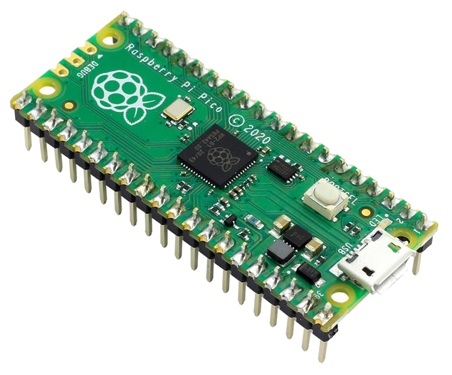
Connectors J1 and J2 are regular 0.1" spacing un-shrouded single row male headers. Longer pieces can be obtained, and easily cut to 14 and 12 pins in length to fit in J1 and J2 positions. Obviously, one can avoid using connectors on these locations by soldering wires directly into the holes. It is suggested, though not mandatory, to use two sets of 20-pin 0.100" (2.54mm) mating connectors to connect the Raspberry Pi Pico to the board. This will allow removal and replacement of the processor board. The 7805 voltage regulator (U9) is mounted horizontally (flat) against the PCB surface. A thermal pad or some thermal grease must to be used between the regulator body and the PCB pad. Note that the tab needs not to be electrically insulated from the PCB metal pad, as it is a desired ground connection. It is recommended to mount BZ1, the magnetic transducer, on the bottom side of the PCB. This will allow to more easily direct the sound through a hole drilled on the enclosure bottom panel. To optimize the transfer of the sound, the PCB standoffs should be selected so that their length approaches or matches (without being shorter than) the magnetic transducer height. Note also that the transducer has a polarity to respect, and a (+) sign is shown on both the transducer and the PCB. Both should align.
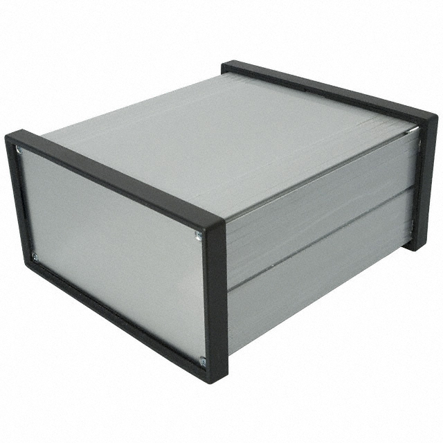
A metal enclosure should be used. This helps to contain EMI radiation from the micro-controller. A suggested enclosure is a Bud Industries EX-4522, 176 x 155 x 80 mm, extruded aluminum box. This is a rather expensive enclosure; it still shows the type of box one may want to use. The enclosure is much larger than the board, and this is suggested to allow easy routing of the internal cabling, and to provide enough front panel surface to accommodate the LCD display.
The Arduino firmware is written to be compiled in the Arduino IDE environment. The Arduino IDE software must thus be installed to a computer. The software is available for Windows, Linux and MacOS operating systems. Visit https://www.arduino.cc/en/software for more details on how to proceed. Support for the Raspberry Pi Pico must also be added in Arduino IDE. Consult this Instructables link for more details on the prodedure. The Arduino firmware (a.k.a. the sketch) uses the following non-standard libraries:
The Arduino sketch for this project can be downloaded from my GitHub page.
Once
the compiled
sketch is uploaded
and running onto
the Raspbarry Pi,
system
configuration can
be performed. For
that task to be
completed, power
must be
applied to the
controller
board.
A command interface is available via the Raspberry PI Pico USB port to configure the controller. This must be perfomed before connecting the controller to a remote antenna switch. Any terminal program (Tera Term, HyperTerminal, Putty, or similar) run on a computer will allow interfacing with the controller. The USB-serial connection will show up as a "COMxx" port in Windows ("xx" being the COM port number). A search in the Windows Device Manager will reveal which COM port number is assigned to the controller box. In Linux, the port will show up as "/dev/ttyACMxx". The /dev/ directory will reveal which serial port number is assigned to the controller box. The interface uses plain (ASCII) text and is command-driven. The various command fields are separated by commas "," and are terminated with a Line-Feed (New-Line) character, typically produced by the "Enter" key (may need to be configured in the terminal program), and illustrated here with "⤶". An example of command syntax is: A,2,40m Dipole,TX-RX,14,15⤶ Here is the list of available commands with some description of their syntax and usage. A: Configures one antenna A,<2..8>,<a..z/A..Z/0..9>,<TX-RX/RX>,<0..99>,<0..99>⤶ |Ant # | Description | Ant Type | Fmin | Fmax | Example: A,2,40m Dipole,TX-RX,14,15⤶
D,<10..100>⤶
H⤶ L: Lists antenna configuration and parameter settings. L⤶
N,<2..8>⤶ O: Sets the output type to BCD lines or to individual relay (bit) lines O,<BCD/BIT>⤶
P,<Y/N>⤶
Once
configuration
is completed,
the
controller can
be connected
to the remote
antenna switch.
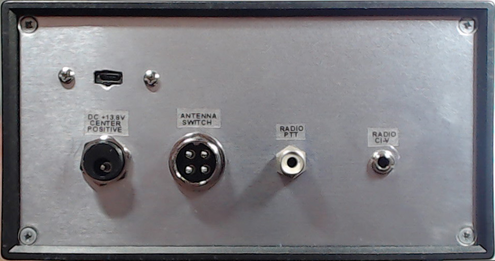
We can also
hook up the
remaining
signals,
namely the
radio PTT
Male-Male RCA
cable and
3.5mm
Male-Male CI-V
cable.
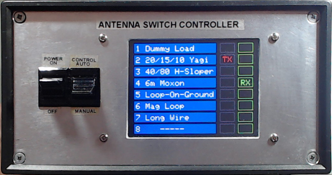
If not already done, the antennas can also be connected to the remote switch. It is recommended to connect a properly sized dummy load to antenna port 1. This offers two advantages. First, there is a protect-to-port-1 feature that, when enabled, transfers the radio to port 1 when a receive-only antenna is selected and the radio goes into transmit. The second reason is that, for some remote switches like the RCS-10, port 1 is the default antenna selection when no control lines are energized. Having a dummy load on port 1 inherently protects the radio from transmitting into the wrong antenna when the controller is turned off. Operation is straightforward. The display shows as many blue antenna banners as there are antenna ports defined. On the right hand side, there are two columns of buttons, the RX buttons (in green when in receive) and the TX buttons (in red when in transmit). Touching the display on an antenna banner or on its corresponding TX button will select the desired antenna (the RX button follows the TX button by default). In case a different receive antenna is desired, touching the RX button of the desired receive antenna will select it. When the PTT is keyed (the radio going into transmit), the controller transfers the radio to the previously selected TX antenna. Releasing the PTT line restores the selected RX antenna. Obviously, when a separate RX antenna is selected and the PTT is keyed, the antenna relays must operate to select the TX antenna. Antenna relays should never switch when transmit-level RF power is carried. This would rapidly wear out the relay contacts. To avoid this situation, there are two possible solutions.
protect-to-port-1 feature is enabled, the controller will transfer the radio to port 1 when the PTT is keyed, the display will show flashing TX buttons and an alarm signal will sound. Releasing the PTT will restore the radio to the receive-only antenna. As suggested, connecting a dummy load to port 1 will protect the radio.
I have operated with this controller during a few contest. Its behavior was flawless. It is a joy to change bands and not have to worry about proper antenna selection. On the 75m band, my Loop-On-Ground antenna often receives better than my 40m sloper. Being able to use both antennas in split Rx-Tx is really a plus. Some of the features do not quite suit you? Make changes to the firmware then! It is very easy in Arduino IDE. The code is fully commented, so you should have no problems understanding what I have done. Supporting other CAT protocols (Yaesu, Kenwood, etc) could be nice! There is even a prototyping area on the board to add some additional hardware if needed. Enjoy! |