|

|
|
|
 |
A Standalone
Icom Remote Antenna Tuner
Controller
|
Author: Bertrand
Zauhar, VE2ZAZ - VA2IW
Page last updated: 2026/07/11
The latest changes
are shown in red font.

|
Have you ever wished you could
use an Icom remote automatic antenna tuner, such
as the AH-4 or the AT-130 without an Icom
transceiver? This page documents a standalone
Icom remote antenna tuner controller box, which
allows to use any brand of radio with an Icom
tuner.
I find the Icom remote antenna
tuners to be good units. I have used the AH-4
and the AT-130 with the IC-7300 radio and have
been satisfied with their performance. However
the uniqueness of their control interface forces
one to pair the tuner only with an Icom
transceiver equipped with the 4-wire Molex
connector tuner interface.
One day, I wanted to use the
half-sloper antenna to which the AT-130 is
connected with a non-Icom QRP radio, thinking
that, at the very least, the tuner would be in
pass-through mode when un-powered. No way, the
antenna appeared to be disconnected from the
tuner! This is only one of the hurdles to face
when trying to use an Icom remote tuner with a
different brand of transceiver. Here are the
workaround steps required to accomplish this (By
the way, if you do not own an Icom transceiver,
you are out of luck anyway!):
- Connect both
the antenna/tuner coaxial cable and the tuner
control cable to the Icom transceiver.
- Set the Icom
transceiver to the desired frequency and
trigger an antenna tune-up the usual
way.
- Once tuning is
achieved, transfer the coaxial
cable to the non-Icom radio and proceed with
operation.
- While
operating the non-Icom radio, keep the Icom
transceiver turned on so that the tuner stays
powered up and in tune (or in pass-through,
depending on what was set on the Icom radio).
- If a band
change or re-tuning is required, transfer the
coaxial cable back to the Icom transceiver,
and perform steps 1-3 above again...
There had to be a
better way to use that tuner-antenna pair. While
searching the Internet for clues on the Icom
remote tuner interface protocol, I found this
excellent document
by Chris-K9EK, which describes the AH-4 tuner
design and operation in detail. With this, I had
everything I needed to try controlling the AT-130
from my electronics bench, not from my IC-7300.
So I put together a controller using a
RP2040-based development mini-PCB and a few solid
state relays (SSR), coded some Micropython, and it
worked!
Note that I have only tested my controller with an
AT-130 remote tuner. However, since I have
implemented the interface protocol described for the AH-4 in Chris-K9EK's
document,
and based on interface
protocol similarities, this controller should
operate correctly with the AH-3, AH-4, AT-120,
AT-130, AT-140, AT-141 and AH-730 tuners. Due
to differences in the interface scheme, this
controller is not usable with the AT-705.
I
have produced a YouTube video that
describes the project and shows the unit
in operation. The link is provided to
the right.
|
|
The proposed Icom remote tuner
controller must accomplish the
following tasks:
- Supply power to the
antenna tuner,
- Send
request to initiate a tuneup action,
- Key
the non-Icom transmitter when requested
by the tuner,
- Send
request to go into tuner pass-through
mode,
- Display
success/failure of antenna
tune-up action,
- Display
in-line/pass-through tuner status,
- Display
an error when the tuner is not present,
- Allow
controller bypassing, restoring
"regular" tuner control with an Icom
radio.
Electronically
speaking, and in a simplified
way, the proposed controller
must accomplish the following
signal handshake with the
tuner. There are two
control signals
interfacing with the
tuner, namely "START" and
"KEY". A low-level, START
pulse is sent to the tuner
to initiate a tuneup
process. The tuner then
replies with a low-level
KEY signal, which is a
request to go into
transmit and send RF. The
tuner then controls the
KEY signal release to
indicate how
successful the
tuner was in
tuning the
antenna.
This process is very well
described with timing figures
in Chris-K9EK's document. In
addition to
the START and
KEY lines, a Vcc
(+13.6 VDC, 2
Amp max.)
supply line
and a ground
make the
4-wire tuner
interface.
To supplement
the basic
tuner
interfacing
above, the
controller
provides the
following
features:
- A
ground-active PTT output line to
control the sending of RF power from
the non-Icom radio at the proper
moment during the tuning process. This
line could typically be wired up to
the CW key,
- A
tuner presence detection by
sensing the current sent onto the
tuner Vcc DC supply
line,
- A
single push-button to control the
tuner,
- LEDs
to provide tuner and controller
status,
- A
toggle switch to select either
this controller or an Icom radio
as the control host.
The
proposed controller circuit
has the following
characteristics:
- It
is based on the RP2040-Zero, a
physically reduced version of the
Raspberry Pi Pico development board. Its
powerful dual-core CPU, low current
consumption and ability to run
Micropython or C language make it a good
choice for most micro-controller
projects.
- For
interfacing with the Tuner's control
lines and the PTT line, it uses
Panasonic AQV212 Solid State Relays
(SSR). They can offer galvanic
isolation, can switch up to 60 Volts
AC/DC at up to 550 mA and are
insensitive to polarity. Moreover, when
purchased from AliExpress, they cost
less than $1 US each.
- The
controller detects tuner presence by
sensing the current sent onto the Vcc
tuner supply line, using a mini-board
hosting an INA226 I2C
current/voltage sensor.
- A
bi-color status LED informs the user of
the tuner status and the tuning process.
Three colors are produced: green, red
and amber (a blend of green and red).
- A
PTT LED indicates when a PTT signal is
sent to the transceiver.
- A
push-button provides control of the
tuner actions.
- A
front faceplate CONTROLLER/RADIO
four-pole toggle
switch allows to either take control of
the tuner, or reconnect it directly to
an Icom radio, restoring "regular"
operation and disable the controller.
- A
10-pin "Phoenix" type connector with
detachable screw-in wire block provides
easy hookup to the tuner, the Icom radio
and +13.8V power.
- The
PCB dimensions allow it to neatly
slide into a standard
88(W) x 38(H) x 100(D) mm extruded
aluminum enclosure, eliminating any
mounting hardware.
Once
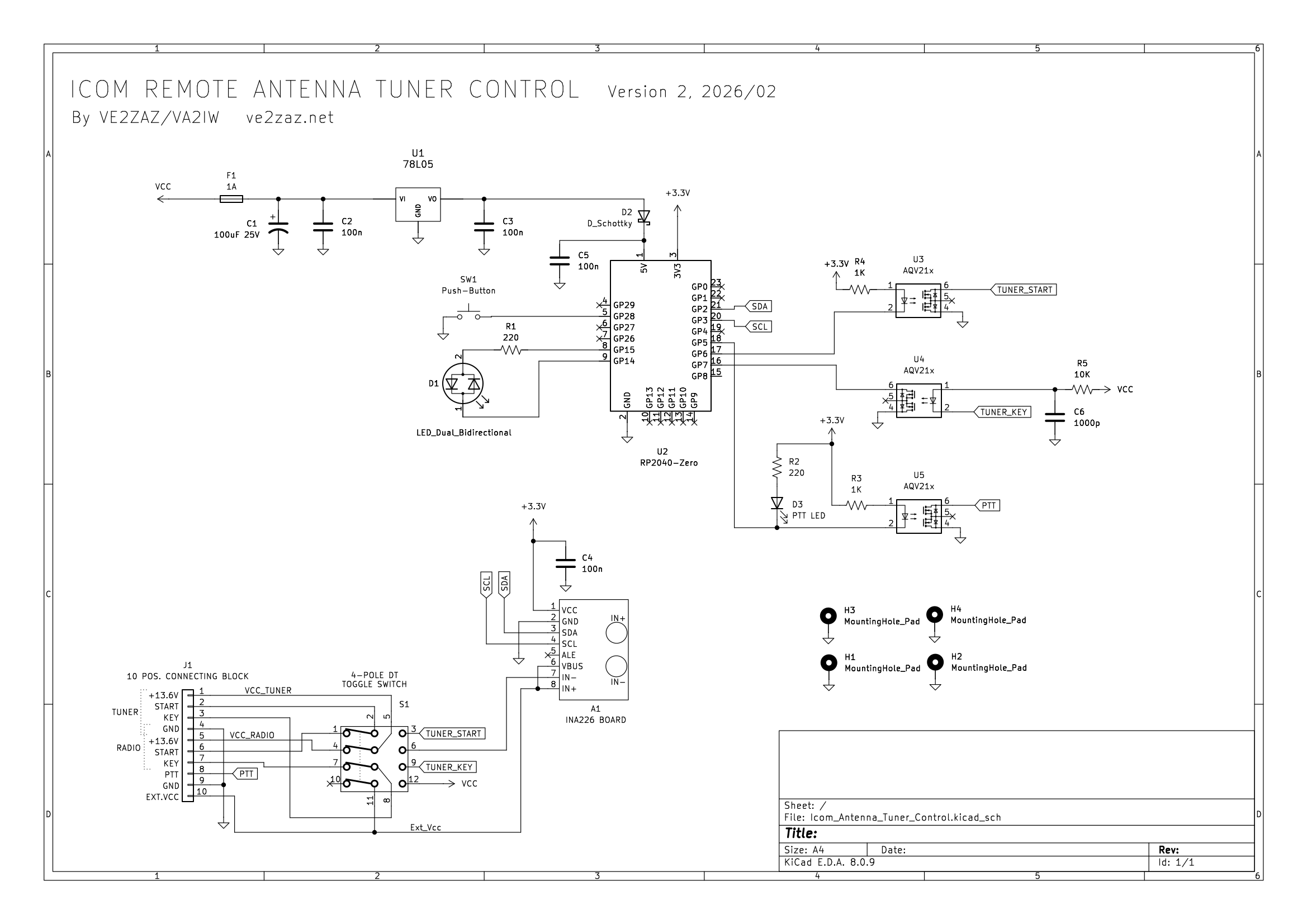
you know the above, the circuit diagram is
relatively straightforward to understand.
Here it is (click on it to zoom in):

The
circuit is powered using a +13.6V external
supply. A 78L05 voltage regulator feeds +5V to the
RP2040-Zero micro-controller board through
a Schottky diode, preventing any back-feed
from the USB port's +5V line. That USB
port is located on the micro-controller
board, so is not shown on the
schematic. The rest of the circuit
uses the micro-controller
board's +3.3V
supply
coming from its builtin
voltage
regulator.
S1,
the four-pole dual-throw
(4PDT) toggle switch provides
full transfer, including the
Vcc supply line, between the
controller and an existing
Icom transceiver. It also
turns off the controller when
the latter selection is made.
|
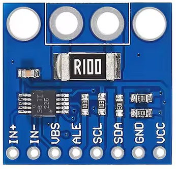
Instead of
having to design in the
INA226 current/voltage
sensor (a fine-pitch SMD
chip) on to the
controller PCB, it was
much simpler to
integrate a small
Chinese-made INA226
board, which also
contains the proper
measurement shunt
resistor. The shunt
resistor in connected in
series
on the
"High-Side" of
the +13.6V tuner supply
line, which allows to
measure the tuner
current consumption, and
thus detect its
presence. The
current
is read over a
two-wire I2C
bus fed by the
micro-controller. |
The selected INA226
board
|
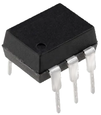
The author has
had previous success
with the
Panasonic AQV
series of
Solid State
Relays; he
used them
often when interfacing
with the
outside world.
They are
cheap, simple,
reliable, and
their outputs
do not care
about signal
polarity or
common-mode
voltage. They
can also
provide
galvanic
isolation
between the
input and
output sides.
Their
implementation
is simple
compared to
using power
transistors,
which require
accompanying
bias and
pull-up
resistors. The
selected
AQV212 SSR is
a good
compromise, as
it can
switch up to 60 Volts AC or DC, at
up to 550 mA, which is suitable for
many ham applications. Other AQV
models with different specifications
are available. |
The AQV212 in DIP-6
package
|
D1,
a bi-color (green/red) LED is
lit by opposing High and Low
logic levels on the GP14 and
GP15 outputs, depending on
which color is required. The
amber color is produced by
quickly toggling the two
control outputs between red
and green. To produce a decent
amber color, the duration
ratio between red and green
may not be 50%; With the cheap
no-name LED used by the
author, it is necessary to
dwell much longer on the red
color. This is done by the
firmware (software). Depending
on which model of LED used, it
may be necessary to change the
dwell time ratio in the
firmware to get suitable amber
color.
The two
LEDs have a
220-Ohms
series
resistor to
limit the DC
current. A 5mA
current limit
is
recommended.
If LED
brightness is
judged
inappropriate,
the R1 and R2
resistor
values can be
changed, as
long as a
maximum
current of 5mA
is met. Note
that resistor
replacement
may affect the
amber color
tone.
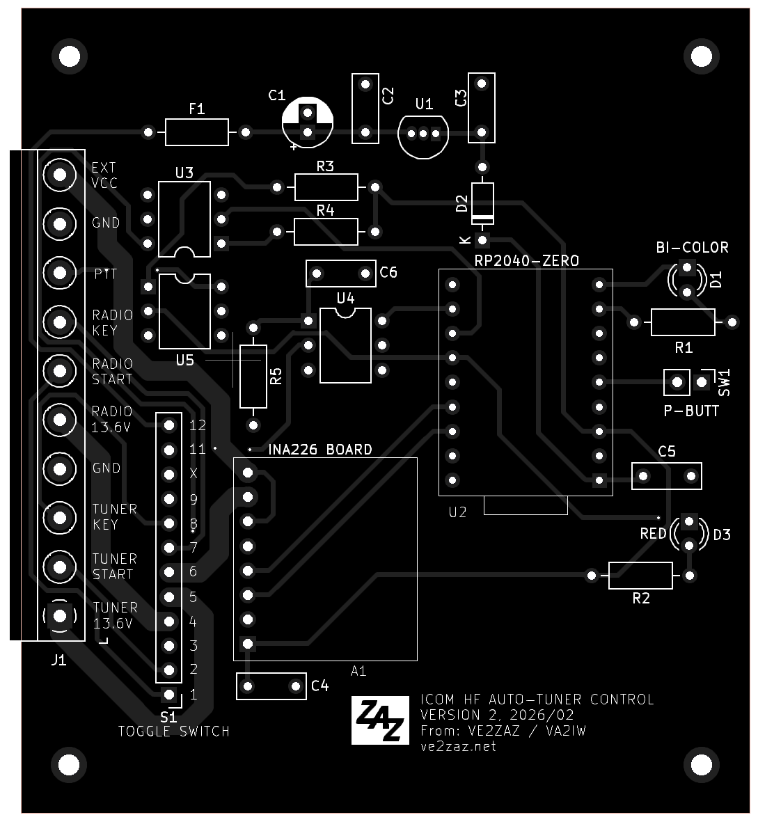
The
project was designed in
the KiCad electronics
design environment. It
implements an all
through-hole design (no
surface-mounted devices
used).
The PCB outline (75.6
mm x 83.5 mm)
was set so that the PCB
fits inside the proposed
aluminum enclosure (see
below), without the need
for mounting standoffs
and screws. The PCB
simply slides into the
enclosure side rails.
Four mounting holes have
also be included for
other integration
approaches.
The PCB bottom side has
the ground plane, which
ensures a low ground
impedance and minimum
signal radiation.
The 10-pin "Phoenix"
type connector is
positioned on the PCB
edge so that it will
protrude on the back of
the chosen enclosure
through its rear
faceplate.
All components are to be
placed on the PCB top
side. Soldering is done
on the PCB bottom side.
Position S1 is meant to
directly receive a
series of wires that go
the the 4-pole toggle
switch. No connector is
necessary. See the
assembly section for
important instructions.
|
|
Here is a list of the suggested components to
assemble this project.
| On-Board
Components |
Qty
|
Reference
|
Value
|
Footprint
|
| 1 |
A1 |
INA226 Mini-Board |
Custom, SIP
pin pitch
|
| 1 |
C1 |
100uF 25V |
Radial
Diam=5.0mm Pitch=2.00mm |
| 4 |
C2,C3,C4,C5 |
100nF 50V
|
Radial
Pitch=5.00mm |
| 1 |
C6 |
1000pF 50V
|
Radial
Pitch=5.00mm |
| 1 |
D2 |
1N5711 Schottky diode
|
DO-35
|
| 1 |
F1 |
1 Ampere
Picofuse
|
Axial,
Pitch=10.1mm |
| 1 |
J1 |
10 Position Phoenix Connecting
Block, detachable screw block,
0.200" pin pitch
|
Pitch=P5.08mm |
| 2 |
R1,R2
|
220 Ohms
1/4W. Adjust resistor value for a 5
mA current into the LED
|
Axial,
Pitch=10.1mm |
| 2 |
R3,R4 |
1 K-Ohm 1/4W |
Axial,
Pitch=10.1mm |
| 1 |
R5 |
10 K-Ohms
1/4W
|
Axial,
Pitch=10.1mm |
| 1 |
U1 |
LM78L05 5V
100mA Voltage regulator
|
TO-92 |
| 1 |
U2 |
RP2040-Zero Board.
|
Custom, SIP
pin pitch
|
2
|
-
|
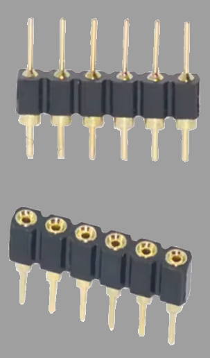
9-pin
male-male "machined" pin header, cut
from a 40-pin strip. Soldered to the
RP2040-Zero micro-controller board.
See details in the Assembly section.
|
SIP
pin pitch
|
2
|
-
|
9-pin
female-male "machined" socket
header, cut from a 40-pin strip.
Soldered to the project PCB. See
details in the Assembly section.
|
SIP
pin pitch
|
| 3 |
U3,U4,U5 |
AQV212 Solid
State Relay
|
DIP-6 |
3
|
-
|
"Machined"-type
IC socket
|
DIP-6
|
| Off-Board Components |
Qty
|
Reference
|
Value
|
1
|
D1
|
LED-Bidirectional Red/Green, 2
leads, 5mm diam.
|
1
|
D3
|
LED, Red, 5mm diam. The same
bidirectional Red/Green LED as for
D1 can be used. Only the red color
will show.
|
1
|
S1
|
Toggle Switch 4PDT
(Four-Pole-Double-Throw), MTS-402 or equiv.
|
1
|
SW1
|
Push-Button SPST Momentary
|
2
|
-
|
LED Socket (Holder), for 5mm
LED
|
1
|
-
|
Enclosure. extruded aluminium,
88(W) x 38(H) x 100(D) mm (see text
below)
|
1
|
-
|
Front enclosure PCB faceplate
(see text below)
|
1
|
-
|
Rear enclosure PCB faceplate
(see text below)
|
8
|
-
|
M3-8mm narrow hexagonal head
screw (see text below)
|
The PCB
has the following
characteristics:
- A
double-sided copper design, all
components are mounted on the top
side,
-
75.6 mm x
83.5 mm
dimensions, qualifies for "special
price" PCB manufacturing,
- Recommended
material: Regular FR-4, 1.6 mm
(0.062") thickness,
- Soldermask
provided for both sides,
- Silkscreen
layer provided for top side, no
silkscreen on bottom side,
- Uses
through-hole components,
easy to put together.
Those
who would like to build this system should
have the PCB made by a reputable PCB
manufacturer (such as JLCPCB or PCBWay).
To complete the order, the
Gerber and drill files must be
transferred to the manufacturer. The ZIP
file containing the manufacturing files
(Gerber and NC Drill files) is provided to
the right.
|
|
The PCB
assembly process is
relatively easy, with
only through-hole
components to install
and solder. No
surface-mounted devices
are used.
The author mounted the
AQV212 SSRs on
"machined" DIP sockets
to facilitate
replacement in the
unlikely case a device
is blown up. Machined
style sockets are more
reliable than cheaper
bent strip style
sockets.
The
same can be said
about the
RP2040-Zero
micro-controller
board. The
author cut two
9-pin pieces
from a
single in-line
male-male
"machined" 40-pin
strip and soldered
them to the
micro-controller
board to act as
a DIP pins.
Corresponding
machined
female-male
header socket
strips are used
on the PCB to
host the
micro-controller
board. This
allows for a
quick
RP2040-Zero
removal /
replacement if
necessary. Note
that the
perpendicular
row of contacts
(opposite the
USB connector)
is not used on micro-controller
board,
and no pins must
be installed on
that row.
|
The type of
"Machined" SIP header
referred to by the author
|
The 78L05
voltage
regulator does
not require
any heat
sinking under
normal
conditions.
The
push-button and the toggle
switch should be mounted to
the front faceplate using
the provided hardware.
The two LEDs should be
mounted to the front
faceplate using 5mm LED
black plastic sockets
(holders).
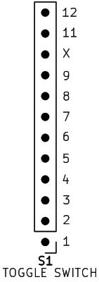
Wiring up
the four-pole
toggle switch
needs
attention. A
series of 11
wires must be
made to link
the S1
contacts on
the PCB to the
actual toggle
switch
contacts. All
wires should
be soldered at
both ends. The
S1 PCB layout
is arranged in
one row of
contacts,
numbered from
1 to 12, as
shown to the
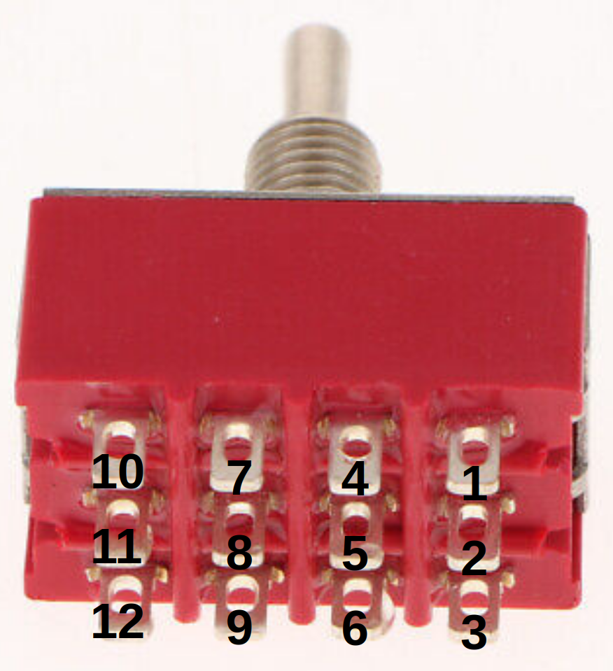
right. The
corresponding
toggle switch
contact
numbering is
also shown to
the right. The
wiring should
follow that
numbering
pattern, PCB-1
to Switch-1,
PCB-2 to
Switch-2, and
so on.
Contacts 4, 5
and 6 should
be run using a
bigger gauge
wire. AWG-20
stranded wire
is suggested,
as the DC
current could
reach 2 Amps.
Other contacts
can use a
smaller gauge,
such as AWG-24
stranded.
Contact 10 is
not used, so
there is no
need to wire
it up.
Proposed
individual
wire length is
9 cm, which
provides just
enough slack
to easily
reach the
front
faceplate,
while still easily fit
inside the
enclosure.
|
S1 - Correspondence
of PCB numbering
vs. toggle switch numbering
|
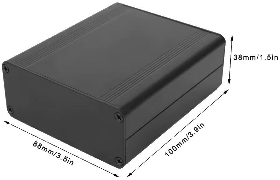
The proposed
88(W) x
38(H) x 100(D)
mm extruded
aluminum
enclosure
is commonly
available on
AliExpress (as
of 2026).
Searching for
"38 x 88 x
100mm Aluminum
Case" should
provide a list
of enclosures
that match the
one used by
the author.
Expect to pay
less than $10
US for one
unit.
The PCB
outline was
chosen to fit
inside the
proposed
aluminum
enclosure,
without the
need for
mounting
standoffs and
screws. The
PCB simply
slides into
the enclosure
side rails.
Four mounting
holes have
also be
included for
other
integration
approaches.
Some glue may
be needed to
maintain the
rear PCB edge
against the
rear
faceplate. A
drop of glue
at the
interfaces of
the PCB and
both rails
should
suffice.
|
The selected
extruded enclosure
|
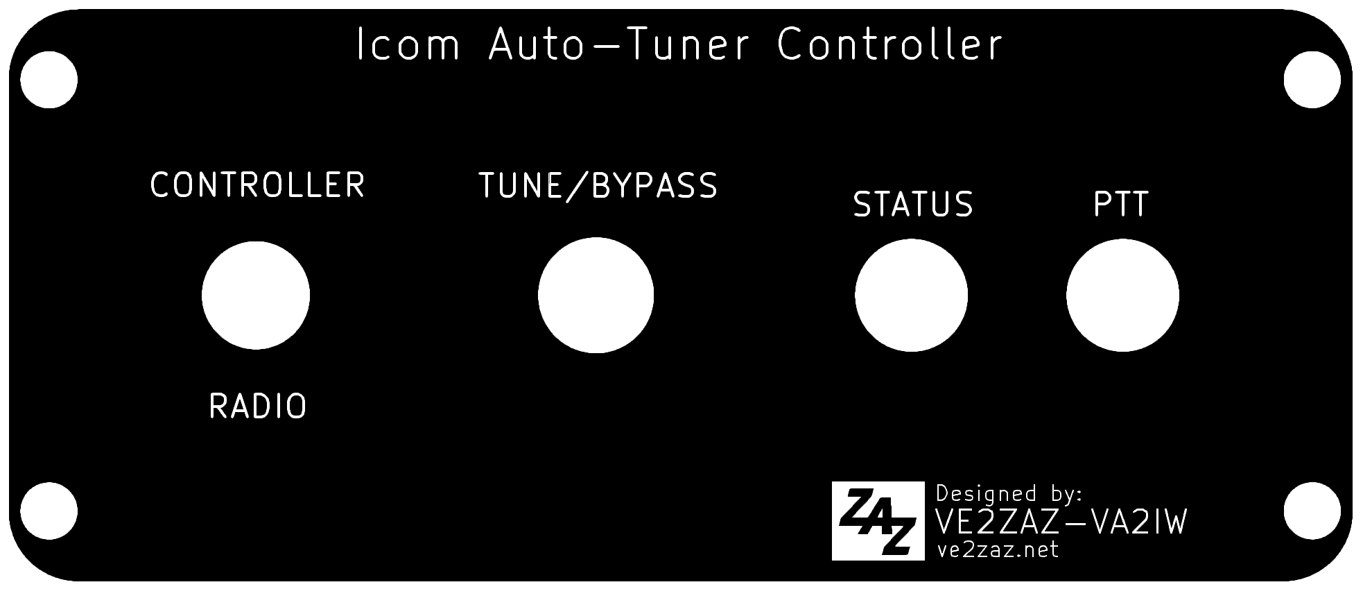
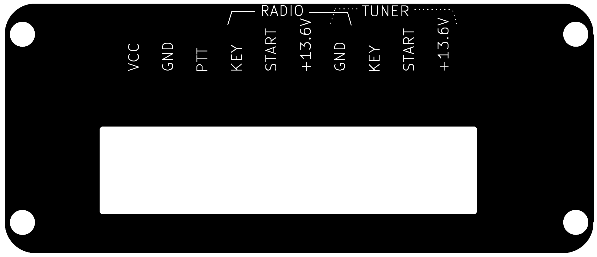
In addition to the
circuit PCB, the author designed
faceplate PCBs to replace the blank
faceplates provided with the
enclosure. When ordered with black
solder resist and white silkscreen,
they color-match the black aluminum
enclosure and give a more
professional look to the project.
The bottom side of the faceplate
PCBs has a continuous copper plane,
which helps reduce signal radiation.
As the faceplates have dimensions
smaller than 100 x 100 mm, they
also qualify for "special price"
PCB manufacturing. Note that the
two faceplates must be ordered as
separate PCBs, hence the separate
gerber zip files provided.
Note that depending on the
connectors, LEDs and switches
used, the faceplate hole sizes may
have to be manually adjusted.
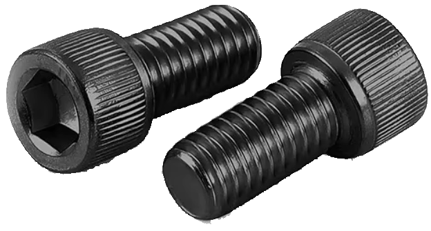
Because the provided M3 size
screws have a chamfered (conical)
head, they do not work well with
the PCB faceplates
unless a chamfer is created in the
holes. The author has instead
elected to use black
M3-8mm narrow hexagonal
head screws, which give a neat
look.
The
replacement M3 narrow
hexagonal head screws
|
|
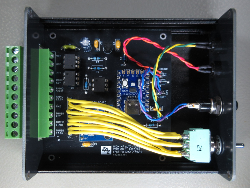
The completed assembly.
Please note that this picture shows a
previous version of the project,
hence some differences with the latest
design, one of which being the number of
wires linking the PCB to the toggle switch.
The
firmware is written in Micropython,
and is designed to run on the
RP2040-Zero micro-controller board.
The Micropython interpreter must
first be installed on the
micro-controller board. Then the
firmware script can be transferred
using a computer editor program such
as Thonny. This procedure is well
explained here .
Important:
It was brought to my attention
that some of the INA226 boards
purchased from Asia respond to I2C
address 0x44 instead of address
0x40. It you are experiencing IO
errors and then code crash when
executing the python code, you
should try address 0x44. To do so,
modify line 67 of the python code
so that it looks like this:
ISense =
ina226.INA226(ISense_I2C, 0x44)
#....
Firmware
Version History
Version 1
(February 2026): Initial
firmware release.
Legal
Note
This
software
design is made
available
under the
following
license: CC
BY-SA 4.0 (Creative
Commons Attribution-ShareAlike
4.0
International).
See this link for
more detail.
In summary:
You are free
to:
- Use,
share and adapt
the design, even
commercially,
You
must:
- Give
appropriate
credit to the
author.
- Distribute
your
contributions
under the same
license.
|
|
INSTALLATION
AND OPERATION
|
INSTALLATION
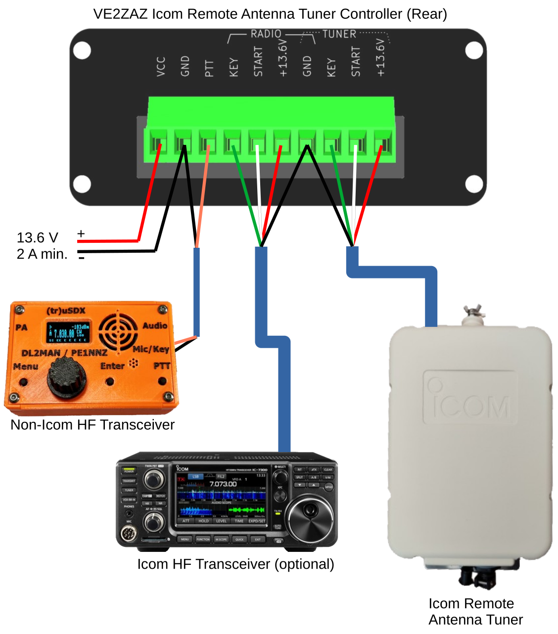
The figure above shows
the required control wiring
between the various components
and the control box. The RF
cabling is not shown.
An easy way to install the
controller into the existing
Icom tuner-transceiver chain is
to cut the Icom-provided cable
about 1 meter from the 4-pin
Molex connector (with the
Icom transceiver
powered off!),
and connect the bare wires to
the control box Phoenix
connector, as shown on the
figure above. The colors shown
correspond to those of the Icom
cable. The wire colors are:
Wire Color
|
Signal
|
Red
|
+13.6V
DC
|
Black
|
Ground
|
White
|
START
|
Green
|
KEY
|
A DC supply of between +13V to
+14V at a maximum of 2 Amps
should be applied to the circuit
PCB on Ext.VCC position on the
Phoenix connector. This will
guarantee a sufficient supply to
the antenna tuner.
The PTT line is grounded when
the antenna tuner requires an RF
carrier to be sent up to the
tuner. The user must wire up the
PTT line to the radio
accordingly. The Morse key input
contacts are one way of wiring
up the PTT line to the radio.
However the Morse key input must
be set up for straight key
operation. The controller
tolerates a maximum of +50 Volts
and a minimum of -50 Volts on
the PTT line. If a PTT
connection to the transceiver is
not possible, the author has
found that manually sending an
RF carrier of 10 Watts maximum
to the tuner while it is in
tuneup does work.
OPERATION
When the CONTROLLER/RADIO toggle
switch is in the CONTROLLER
position, this controller
operates the antenna tuner. When
the CONTROLLER/RADIO toggle
switch is in the RADIO/OFF
position, this controller is
powered down, and the antenna
tuner is operated by the
external Icom transceiver
connected up to the controller
via the rear Phoenix block.
The status LED shows various
operational states using three
colors and some blinking. The
push-button controls whether to
tune the antenna and engage the
tuner inline, or to put the
tuner offline (in pass-through).
At power up,
the tuner is considered to be offline
(in pass-through). The status LED thus
shows a solid-amber color. However, if
no tuner Vcc current is sensed (tuner
not drawing a minimum supply current),
the tuner is considered missing and a
slow-blinking-red color will show
instead. Under such state, the
push-button is disabled. As soon as a
a valid tuner Vcc current is detected,
the tuner is considered present and in offline (in
pass-through) state, and the
push-button action is restored.
Pressing the push-button for more than
one second (a long press) initiates a
tuneup procedure. While in progress,
the status LED shows a fast-flashing
amber color, the PTT LED lights up
and the
PTT line is asserted to electrical
ground. At this point, the tuner
expects to receive an RF carrier with power
in the range of 5 to 10 Watts. If
properly wired up, the PTT line will
put the radio transceiver in transmit.
When tuneup is completed, a
solid-green color is shown when the
antenna tuneup was successful (a match
was found) and the tuner is put
inline. If antenna tuneup was not
successful (no match found), the LED first shows blinking
amber, followed by solid amber,
and the tuner is put offline (in
pass-through).
Pressing the push-button
for much less than one second (a quick
press) forces the tuner off-line. In
that state, the status LED shows a
solid amber color.
If, for any reason, the tuner fails to
initiate a tuneup procedure (no KEY
signal received by the tuner), a
blinking red color, followed by a
solid red color will show on the
status LED. This may indicate that the
tuner is powered up (Vcc current is
detected), but that one of the control
lines is be disconnected. This could
also indicate a problem with tuner
operation.
Here is a table that summarizes
the LED indications.
Status LED
|
Color
|
Tuner/Controller
Status
|
 |
Solid Green
|
Antenna is tuned up and
the tuner is inline
|
 |
Solid Amber
|
Tuner is offline (in
pass-through)
|
   |
Blinking Amber, then Solid
Amber |
Tuner failed to tune up
the antenna, no match found, tuner is offline (in
pass-through) |
 |
Fast-Blinking Amber |
Antenna tuneup in progress
|
   |
Blinking Red, then Solid
Red
|
Tuner not responding to
the tuneup request
|
 |
Solid Red
|
Tuner did not previously
respond to the tuneup request |
 |
Continuous-Blinking Red
|
Tuner not powered up,
defective or not present
|
 |
Extinguished
|
Controller is un-powered,
or Controller/Radio toggle switch is set
to Radio/OFF
|
Here
is a table that summarizes the push-button
action:
Push-Button
Action
|
Tuner/Controller
Action
|
Long push
(> 1 second)
|
Antenna tuneup is
initiated |
Short push
(< 1 second)
|
Tuner is put offline (in
pass-through) |
The
author would appreciate reading back from
the experimenters who build this project. This
will allow to improve this page and the
project by providing additional clarification
if necessary. Thanks!
|