| |
 |
A CW Sidetone
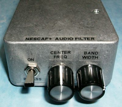
Bypass for the NESCAF Audio Filter
The NESCAF
audio filter is a small and low cost circuit that works great. It is a
good addition to any amateur radio setup. It is especially useful with
radio receivers or transceivers that lack an optional CW filter.
One feature this filter lacks though is a bypass path for the audio when transmitting in CW. This would allow to hear the CW sidetone geneated by the radio through its speaker. So I have come up with a simple solution to this issue.
Referring to the altered NESCAF audio filter schematic diagram below, all added connections and components are shown in wider/bolder black color. The bypass path is provided by a reed relay. The relay simply bridges the audio input signal to the output audio amplifier. The relay coil is energized via the ground return path provided by the Morse code key. The silicon diode and the zener diode insure that interaction with the radio is kept to a minimum. On the audio path, a 10K resistor is inserted to reduce the gain and match the audio level seen when the filter is inserted. A coupling capacitor is also inserted to block any DC current from flowing. Grounding the "Morse key" terminal will operate the bypass relay. 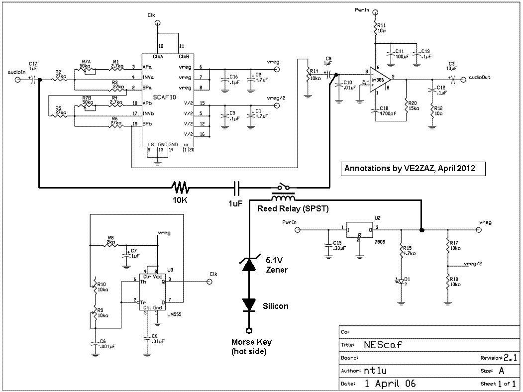 Click on figure to enlarge it
Nothing is really critical in the implementation, and you may want to experiment with the component values to suit your needs. The following are things you should consider when adding this feature to the filter.
The
following picture shows the added circuitry, with the reed relay (in
blue) sitting on top of the filter chip. All connections that are part
of the add-on circuit are made with the thin red wires.
 Click on picture to enlarge it
Operating the add-on bypass circuit
is a matter of connecting the "Morse key" terminal of this circuit in
parallel
with the radio's key input (hot wire and ground) and on the the morse
code key. Please observe
polarity.
|