|
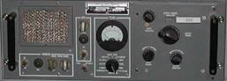
AM-6155 / AM-6154 Conversion to 432 MHz By: Bertrand Zauhar, VE2ZAZ
Page last updated: 25/12/2023 This
page
presents my experience in converting an
AM-6155 (AM-6154) FAA amplifier to the UHF
Amateur Radio 70cm band. My intent is not to
repeat everything that is well documented on
other websites, but instead to supplement
whatever others have done with my own
findings. By following the links I provide and
by executing the additional steps I describe,
the user will have a very good and reliable
linear amplifier capable of producing 350-400W
of clean RF output on 432 MHz. The
latest updates are shown in italic font. Please
report any
broken links to me. Thanks!
The
FAA used the AM-6155 in the 1970's and
1980's with ground-to-air transmitters. They
were designed to cover 225-400 MHz at 50
watts AM continuous output. With only a few
hours of work, and a few extra parts, they
are capable of 400 watts RF output on 144
MHz, 222 MHz or 432 MHz in SSB/CW at Amateur
Radio duty cycles. This amplifier used
either an Eimac 8930 or an Amperex DX-393
tetrode tube. There are tons of these
amplifiers currently in circulation mainly
in North America.
Web links to the original ITT (the manufacturer) AM-6155/6154 manual and circuit schematics can be found below:
Basic Chassis conversion The main chassis (power supply) conversion is described in numerous web locations. Since there were several iterations of the conversion developed over the years, reading the various websites becomes confusing and even contradictory in some cases. Luckily, I found a web link by W3RJW that simplifies everything. As a main reference, use his chassis conversion webpage. But apply the following modifications to his instructions provided in the link:
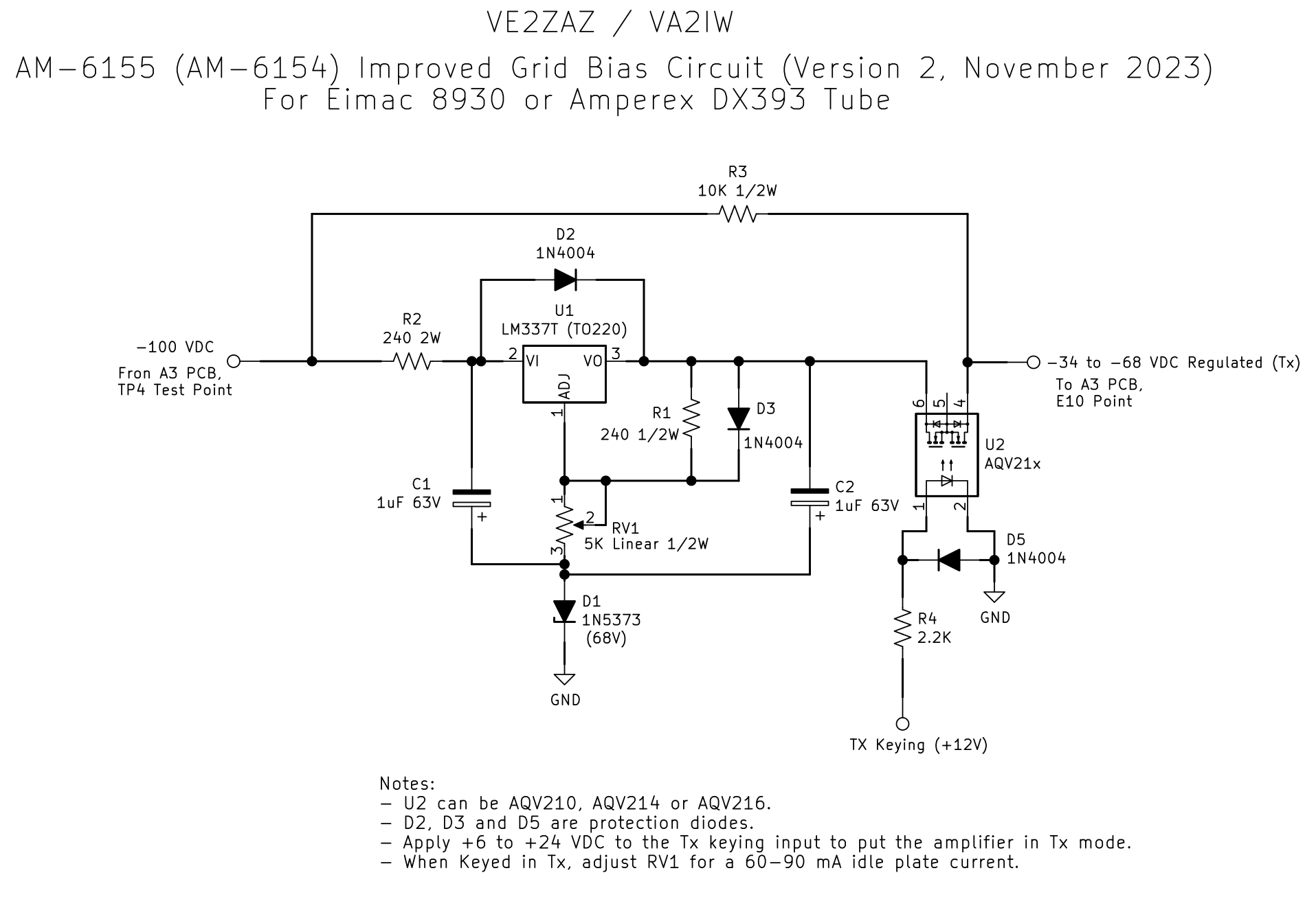
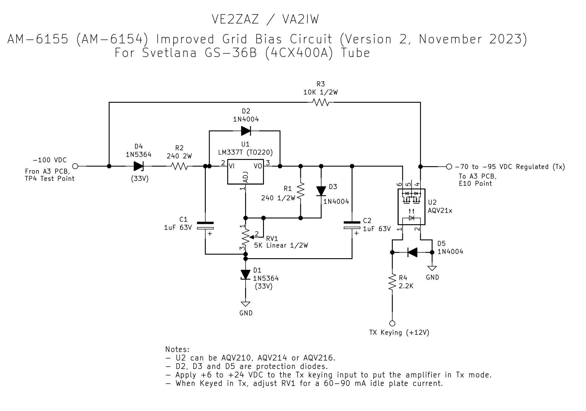
The first tests I performed with my AM-6155 on 432 MHz revealed a major non-linear output response. The output RF power was not tracking the input RF power. The unit picked up gain as the input level increased. I noticed a major sag of the grid bias voltage when keying down at full power. This voltage would go from -78V to -50V in a matter of a couple of seconds. This is due to inadequate grid bias regulation. Apparently, this is worse at 432 MHz due to decreased tube efficiency. If you intend to operate this amplifier in a linear mode (AM, SSB), you MUST perform a grid bias modification. I still definitely recommend that you perform the mod in all cases and for all amateur bands. A glimpse at the original circuit schematics revealed a resistive divider and a potentiometer as the way to set the bias. Looking around on the web, I found K4HV's bias circuit proposal. That circuit improves the regulation somewhat, but requires numerous resistor values and a 2W pot which is rather expensive to acquire. So I decided to design my own. With my improved grid bias supply, the voltage is now rock-solid and RF response is linear!
1- On the existing A3 assembly printed circuit board, cut one of the two leads of the following resistors and lift up their end so that the cut off lead no longer makes contact:
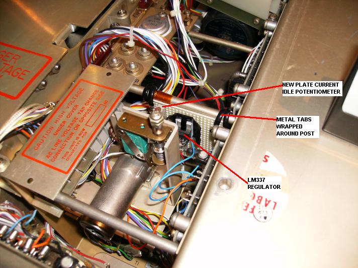
3- Solder the new grid bias circuit input wire to the TP4 post on the A3 assembly printed circuit board. 4- Solder the new grid bias circuit output wire to the E10 post on the A3 assembly printed circuit board. Do not disconnect the existing orange wire form the E10 post. 5- Run the T/R Keying wire to the back panel as suggested in Step IV-D of W3RJW's chassis conversion webpage. Applying any voltage between +6 V and +24V to the Tx Keying signal will switch the amplifier grid bias into Tx mode, which allows the idle plate current to flow. The grid bias adjustment is made with the amplifier powered up and keyed in Tx mode (no RF at the input). Adjust the trimming potentiometer for an idle plate current of between 60 and 90 mA. It should normally represent ~ 20% of the maximum plate current. I set mine to 80mA. That's it. Solid output and good linearity. Chassis Re-Wiring to 240V AC I suggest re-assigning the amplifier so that it runs on an AC mains input to 240V. Considering that we run the amplifier beyond its specified limits, this will give some relief to the transformer primary winding. The switch to 240V is done by re-positioning jumpers on the two TB1 terminal blocks. There is one terminal block on top of the A3 Assembly (hidden under a removable "Caution High Voltage" plate) and one block next to the power transformer under the long high voltage hinged cover. Jumper assignment for 240V is the same for both blocks:
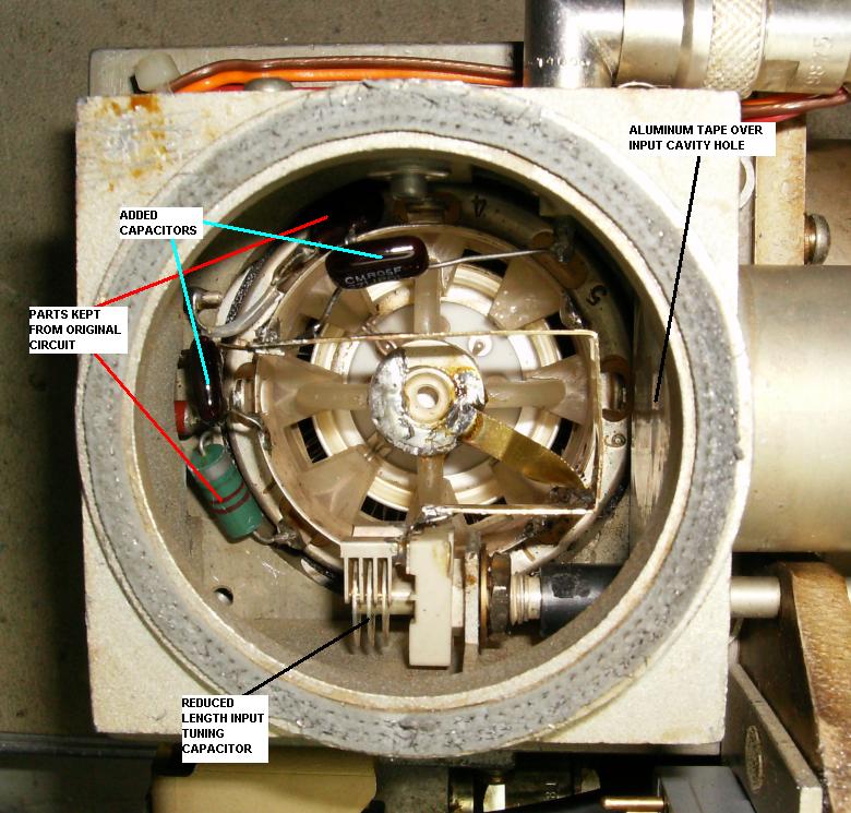
For the RF plugin conversion, make sure you use the circuit schematic that corresponds to the right type of plugin you own. There exists a VHF (AM-6154) plugin and a UHF (AM-6155) plugin out there. Select the proper schematic page, otherwise it will be confusing when doing the grid compartment component removal process. RF Input Compartment Conversion For Input (Grid) circuit conversion, I basically followed W3RJW's modification page, steps 1 to 10, with the following adaptations:
Remember to disconnect and remove the low pass filter module and the directional coupler module from the output coaxial line. Replace them with N-Female/N-Female adaptors.
I have also implemented and tested an improved grid bias circuit to support the Svetlana 4CX400A (GS-36B) tube requirements. Since the original Eimac and Amperex tubes are becoming scarce, this tube is a good substitute. I purchased a pair of New Old Stock (NOS) GS-36B (4CX400A) on eBay for around $100 per tube, delivered. My initial thoughts were that I would get additional output power over the Eimac 8930 just by comparing the specs. Before we go any further, let me warn you that you MUST CONDITION any new transmitter tube before applying high plate voltage to it, otherwise the tube will arc internally and this will damage the tube and your amplifier. I learned this the hard way! The conditioning procedure consists of running the tube with the amplifier powered on (filament on, fan running, no plate voltage, no RF at the input) for a few days (I suggest 4 days). This allows the getter to capture any remaining gas molecules inside the tube. Feel free to search the web for more information on power tube conditioning and the getter electrode.
One thing I noticed while re-installing the chimney and cavity cover is that the chimney protrudes outside of the cavity by a millimeter or so. Once installed, the 4CX400A tube stands probably slightly taller than the original tube. This causes the cover to not quite sit on the cavity flange. When tightening up the four cover screws, go gradually on the tightening, working diagonally and trying to maintain equal tension on the four screws. Do not overtighten, as this force gets transferred to the tube itself. Once complete, there will still be a small gap between the cavity and its cover, but certainly not enough to disturb cooling. If RF leakage is a concern to you, you may want to use an RF gasket to fill the crack, or simply use aluninum tape all around to cover the gap. I did not care since the RF plug-in sits inside the chassis. Results Well, the bottom line is to not expect a big improvement over the original tubes with the 4CX400A. From what I could see, you can get maybe 25-50W more, so 350-400W but the plate current is significantly higher too. This shows an even less efficient configuration compared to the original tubes, which is not high to start with. The power supply is the main limitation in trying to push more output. Cooling is also limited with the stock blower. While testing, I pushed the input power a bit too far (more than 15W), and blew up the three panel-mounted zener diodes ($10 each) that set the screen bias and a few other resistors blew up as well. Simply put, the AM-6155 chassis is not designed for such stress. I suggest you settle for 300-350W output in CW.
In a nutshell, Dale suggested killing the screen bias instead of steering the grid bias. That voltage is +390 VDC. Being positive, it is inherently more stable to work on, as a failure of that screen voltage will most likely mean the voltage going to zero, essentially eliminating any possibility of DC plate current. In retrospect I think this would have been a better approach. Now it involves a relay which can withstand 400 VDC, which is not cheap or common. However some solid state relays can do that. Here is one available at Digikey for less than $7 US: The CPC1983Y. That solid state relay and a high value pull-down resistor on the output, like described on page 3 of AF1T's document, would do the trick. A +12 to +14V signal applied to the SSR's input through a limiting resistor would do the witching, while providing total isolation, a plus compared to the previous grid bias solution. This approach does not eliminate the need for the improved grid bias circuit described above, but that grid bias circuit would be always on, permanently tied to the grid bias line, and no TX-Rx keying would be needed on the grid bias circuit. I would definitely like to hear back from those who try this approach!
With the above conversions performed, I get the following performance on 432MHz: Original Eimac or Amperex Tube CW/SSB: 15W input yields 325W output @ 300mA of DC plate current. I can push to 375W output for short bursts. JT-65: 250W output @ 250mA of DC plate current is the maximum I can run in 50-second continuous transmissions without the overheat protection tripping. Svetlana 4CX400A (GS-36B) Tube CW/SSB: 15W input yields 350W output @ 350mA of DC plate current. I can push to 400W output for short bursts. JT-65: Like with the original tubes, reduced output power by at least 100W in order no to trip the overheat protection. AC Mains Current In the 3A to 4A range @ 240VAC. |