|

|
|
A Bluetooth Headset Interface with built-in
PTT for Amateur Radio
By: Bertrand
Zauhar, VE2ZAZ
Page last
updated: 02/02/2010
This
page presents an interface to a Bluetooth headset for
Amateur radio application. The key advantage
in my solution is that the
Bluetooth headset's answer/hang up push-button
can be used to control
the
radio PTT. This is very convenient inside and
around the shack.
The enforcement
of city and
provincial/state by-laws force the hams to
use a hands-free microphone
as replacement to the classic hand mike.
The Jabra A210 interface is the best
approach for add-on Bluetooth
capability to amateur radio transceivers. It
is sold as an interface
for
non-Bluetooth capable cell phones, but can
be quite easily adapted to
interface radio transceivers. The following
hyperlinks will give you
the background behind interfacing to ham
radio. I am very thankful to
those who did the early work:
In addition, here is the Jabra
A210
interface
instruction manual.
I
recommend that you consult the above links
before continuing on.
There is
one feature
in the Jabra A210 device that is not
documented anywhere and that has
not been proposed by anyone so far for PTT
support. It is the ability
for the A210 to pick up a cell phone call or
hang up using the
Bluetooth handset push-button. I have
discovered this after analyzing
the literature on wired headsets and on the
A210 itself. With proper
interfacing, this feature can be used for
wireless PTT support. In a
nutshell, the A210 sends a 400-millisecond
short to ground on the phone
plug tip every time the headset push-button is
depressed. This cannot
be sensed or perceived unless a weak pull-up
resistor is populated on
that signal.
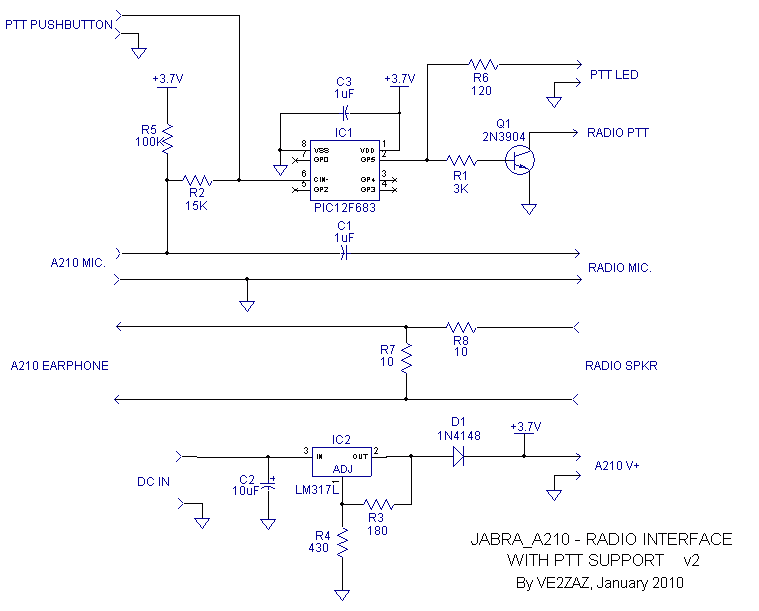
In order for this feature to be used for PTT
support, a D-Type
Flip-Flop function must be added. Pressing
once engages the PTT,
pressing again dis-engages the PTT, and so on.
I have decided to
implement this function in a PIC
micro-controller. The PIC12F683 is a
low cost 8-pin device; this is smaller than
the 14-pin MC4013 dual
D-Flip-Flop chip. I also use an analog
function of the PIC, its
comparator input, for better noise immunity
and less loading on the
audio line. I have also added a timeout timer
that will release the PTT
if it is engaged for more than 2.5 minutes.
This could prove useful if
the bluetooth link is lost.
Since a 12V DC source is provided in a mobile
application, I have added
a +3.7 V DC voltage regulation that will work
with anything higher than
+7 V DC.
02/02/2010 -
Added notes
specific to West Carleton Amateur Radio Club
group project. Others may
disregard.
10/01/2010 - R5
value changed to
100K ohms. R7 and R8 value changed to 10 ohms
(easier to procure). Schematic
diagram (version 2) and
parts list updated accordingly. PIC firmware
updated to version 2. A few assembly
notes added.
10/01/2010 - R3
and R4 had their
value swapped on the schematic and on the
parts table. The PCB view and
PDF files have been updated.
05/01/2010 - Initial Release
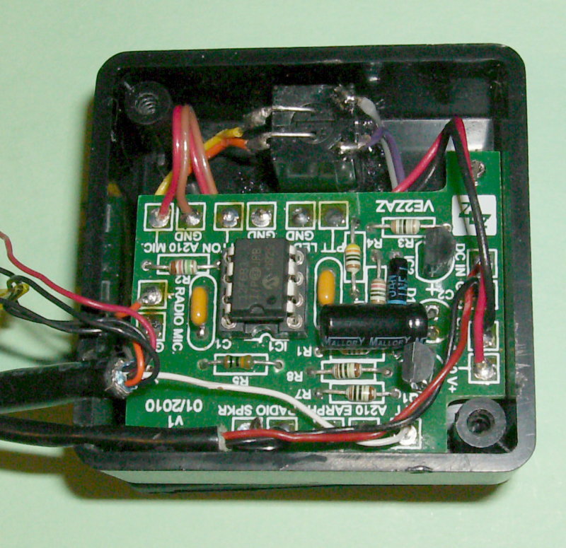
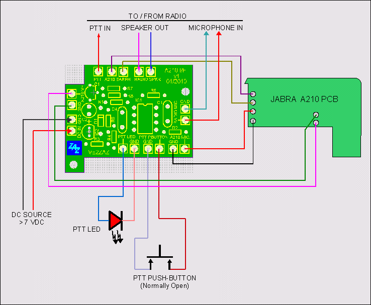
My
Jabra A210 - Radio interface
schematic is shown on the right hand
side. The circuit is quite
straightforward. The headset microphone
audio
signal flows from left to right, from
the Jabra A210 to the radio
microphone input. A coupling capacitor
C1 is added to eliminate
possible DC contention on that line. The
headset earphone audio flows from right
to left, so from the radio
speaker to the A210 earphone input. I
have populated an optional
attenuator made of R3 and R4 to reduce
the audio level going into the
A210.
|
Click
on
the
figure
to
enlarge
it.
|
Note that the
speaker ground
and the headset microphone ground
are kept separate. Inside the Jabra A210,
there are separate pads on
the
PCB. This is to keep any ground loop (hum) to
minimum.
The pull up resistor that allows to produce
the pulse to ground is R5.
The pulse is detected by the PIC
micro-controller through R2. A wired
PTT push-button provides a local PTT
function identical to the headset
push-button. The PTT output sent to the
radio is provided by Q1, an NPN
open collector transistor. When the PTT is
active, the transistor
shorts the radio PTT line to ground. There
is also an optional PTT LED
line provided for visual acknowledgment of
the PTT state.
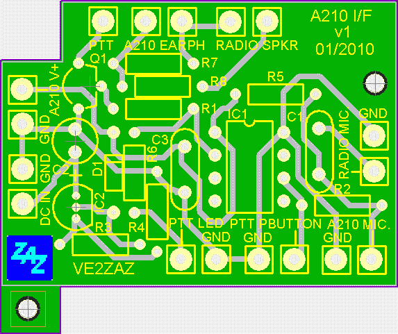
I have
created a PCB layout that
custom-fits a Hammond 1551RBK
enclosure. This
is a
neat and compact solution. The PCB
layout is shown on the picture to
the
right.
-
The PCB
is made of
single-sided copper clad
glass-epoxy material of 0.062"
thickness.
-
The
copper
pattern resides on the PCB
bottom side. The components
are located on
the top side.
-
When
hand-making the
PCB, drilling of
holes is required to solder
the components to the copper
pattern.
|
Click
on
the
figure
to
enlarge
it.
|
If
you wish to make this PCB yourself, here is
the PCB copper layout
file. It prints on letter-size paper. When
printing in full size (no
scaling) the dimensions and proportions should
be accurate.
I wrote the PIC12F683 firmware in ANSI C. I used
BoostC and the
BoostIDE environment. These are free compiler and
integrated design
environment available from SourceBoost
Technologies. The code is commented so that
you can understand what
is happening. Have a look at the .c file. Here is
the whole design
directory.
Some
preparation
is required in order to use the Jabra A210
Bluetooth
interface in my application.
- Open up the unit.
This is a delicate
task if you want to preserve the looks of your
A210. Using a sharp
knife, carefully crack open the casing. It is
easier to start on the
side where the casing has a long recessed
slot. Work your way to the
corners and the ends. Go gentle. The glue
should give pretty
easily. Watch out for the flying white button!
Work over a table and
make sure to recover the white button that
falls off when you spread
the two covers.
- Remove the old
battery. If you
intend to connect
the unit to the voltage regulator for external
battery operation or
12V DC, you
must disconnect and remove the old battery.
Simply cut off or desolder
the battery wires. There is hot-melt
glue on the contacts so take that off
first. The
battery is also glued to the casing; use a
small flat screwdriver
and gently
pull it off.
- Remove
the coiled signal cable.
Simply desolder or cut off the
four wires attached to the PCB.
There is
hot-melt glue on the contacts
and wires so take that off
first.
Preserve the rubber grommet to
plug the cable hole after
completion.
Simply cut off the
cable from the grommet with a
sharp knife.
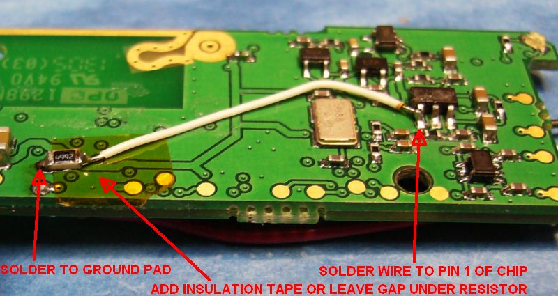
- Implement
VE3LC's
modification.
The
A210 normally transitions to a
power-saver mode after 60
seconds
without any audio fed into it.
For an amateur radio
application, we do
not want this. To keep it alive,
install a 47K resistor as shown
on
either of the pictures to the
right. I recommend using a
surface-mounted resistor. I used
an 0805-size resistor and some
AWG-30
"wire-wrap" wire. Implement the
solution you
are more comfortable with. In
either case, the result is a 47K
resistor
connected between pin one of
that chip and ground. If you are
still
unwilling to deal with
surface-mounted components,
implement VE3LC's
mod using a regular leaded
resistor as shown in his
PowerPoint
presentation.
|
Click
on
the
figure
to
enlarge
it.

Click
on
the
figure
to
enlarge
it.
|
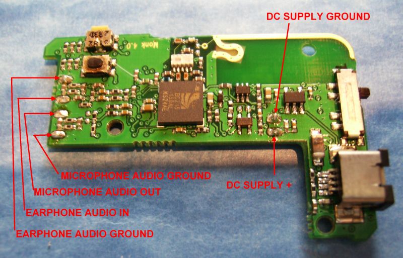
- Attach
new wiring.
Desolder any old pieces of wire from
the PCB and connect new wires to
the six PCB pads shown on the
picture to the
right. Use long enough wires to
allow interconnecting with the
interface PCB inside the Hammond
box. Using colored wires is a good
idea.
- Drill a hole in the A210 to
feed the wires
to the
Hammond enclosure. You
want to send all the wiring to the
Hammond enclosure located
underneath. Drill a hole through the
bottom
cover that is big
enough to accommodate all the new
wires. The best location is somewhere in the center of
the area where
the battery used to be located.
|
Click
on
the
figure
to
enlarge
it
|
PUTTING
EVERYTHING
TOGETHER
|
- Assemble the
interface PCB as per
the parts list provided below.
- I
highly
recommend
using an i.c. socket in the PIC
micro-controller location.
- The
PCB is quite small, so I had to keep the pad
size to minimum. This
makes re-work (replacing components)
difficult without damaging the
pads and traces. Make sure that the
components are in the right
locations before soldering!
- Depending
on
the electrolytic capacitor package used in
C2, it may or may not fit
in the proposed enclosure when mounted
vertically. Install C2 last and
bend its leads 90 degrees to mount it
horizontally (parallel to the PCB
surface), and above the other components.
- Install
the
PIC micro into its socket only after the
entire soldering process
is completed.
- Install
the momentary PTT push-button
and
the PTT LED (optional) on
the top face at one extremity of
the
Hammond enclosure. Make sure
that the PCB will still fit
inside the
enclosure with the proposed
push-button and LED locations.
See the
picture to
the right for the proposed
location. Note that I used a
push-button
with built-in LED.
- Drill
a hole to feed the wires from
the
A210 inside the enclosure. You
want this hole to be located on
the top face of the enclosure,
underneath the interface PCB.
Position
that hole to
align with the hole on the
bottom cover of the A210 so that
the A210 is
neatly positioned on top of the
enclosure. Use the
A210 bottom cover to mark the
location on the enclosure for an
exact
hole line up.
Once again see the picture on
the right
hand side for a suggested A210
location.
|
Click
on
the
figure
to
enlarge
it.
|
- Drill a hole on
one side of the Hammond
enclosure to feed the DC power cable
and the radio speaker cable.
- Feed the A210
wires inside the enclosure.
- Attach the A210
to the top of the Hammond
enclosure. I used Coax-Seal putty.
Use something that can be easily
removed. Velcro is also fine.
Remember that the Bluetooth pairing pin-hole
is located on the bottom
cover of the A210!
- Install the
interface PCB. Bring
all the wiring underneath the PCB and above it
by routing it to one of
the open corners in the Hammond enclosure.
- Solder
the wires and cables to the
proper
locations.
Follow the wiring diagram shown
to the right. If you do it
right, you
should be able to take the PCB
out of the enclosure when all
the wiring is still attached.The
result should look similar to my
assembly shown below.
- Install
the proper connectors for the
radio
interface. Follow your
radio manufacturer's wiring
instructions
or the radio schematic diagrams
for the microphone connector
pinout.
|
Click
on
the
figure
to
enlarge
it.
|
|
|
VERIFICATION
AND
ADJUSTMENT
|
Make sure that
everything visually checks OK. Do
not connect the cables to the radio yet. Apply
power to the unit. Repeatedly press the
PTT push-button. The PTT LED should alternate
between on and off
states.
Press on the A210 power button until its blue
LED flashes a few time.
From that point on the A210 LED should flash
once every few seconds.
Now is the time to pair up the A210 and your
headset. Using a
needle-sized object, press the pairing button in
the hole under the
A210 casing. The blue LED should become solid
lit. Now put your headset
in pairing mode. This is usually done by
pressing the headset
push-button for about 10 seconds, but follow the
headset instruction
manual.
The pairing should be completed in about 20
seconds. This will be the
case when the A210 LED returns to a single flash
every few seconds. Now
turn off both the headset and the A210.
At this point, connect the radio speaker and the
microphone connector.
Go to an unused frequency on your transceiver.
If the SSB mode is
available, select it. This will reduce the RF
interference you produce
when the PTT is engaged.
Now turn the A210 back on. Then turn on the
headset. The radio should
transition to Transmit mode and the PTT LED will
turn on. This is
normal and inherent to the Jabra A210
push-button operation. Release
the
PTT by either pressing the headset push-button
once or pressing the
wired PTT
push-button on the Hammond enclosure.
As far as audio adjustments go, listen to an
occupied frequency and
increase the speaker volume on the radio. You
should hear the radio
speaker audio into the headset earpiece. For
transmit audio, you need
to monitor yourself into another receiver or ask
someone to help you.
There is a 3-position microphone slide switch on
the A210. Select the
switch position for best transmitted audio.
|
OPERATION
AND
PERFORMANCE
|
You are now
operating your Bluetooth headset on
Amateur Radio! There are a few things you need
to know when using your
headset on the air. Here they are:
- There
is
a
one-second
delay
between depressing the headset push-button
and
the radio PTT action occurring. This delay
is generated by the A210 and
there is nothing that can be done to reduce
it. In a typical simplex or
repeater
conversation, this is not much of a problem,
but forget about
contesting using the headset push-button! If
you need fast PTT action, just use
the wired PTT
push-button instead. Note
that the headset
microphone audio is always present at the
radio connector.
- Powering
up
the
Bluetooth
headset
will put the interface in transmit mode, the
LED will turn on
and so will the transmitter. Just remember
to quickly revert to receive
by pressing on the PTT push-button once.
Again, the A210 causes
this and nothing can be done to remove it...
- I have verified
that the
range is around 10m (30 feet) in line of
sight. Walls and floors will reduce the range
though. So I would not
claim
that you can walk around everywhere inside the
house and expect it to
work flawlessly. But "inside and around the
shack" is probably a better
way to
describe the range.
- I
have
noticed
that
there
may be a low-level constant-pitch whining
noise
present on the transmit audio. The intensity
of that noise seems to be
dependent on the headset type used. It is
quite low, certainly not
enough to annoy the people listening to you,
but it may show up.
Once
you
know these things, you can enjoy using your
bluetooth headset on
any amateur radio transceiver like I do in the
car. I actually like it
even better inside and around the shack. I can
walk around and still
provide
input on our local VHF SSB weekly net without
having to run to the
radio every time they turn it over to me. Very
convenient!
A210
Bluetooth - Amateur Radio interface Parts
List
(Version 2)
| Qty |
Designation |
Description |
| 2 |
C1, C3
|
1uF,
10V ceramic capacitor
|
| 1 |
C2 |
10uF, 25V electrolytic
capacitor, radial
|
| 1 |
D1
|
1N4148 or 1N914 silicon diode,
or equivalent silicon diode.
|
| 1 |
IC1
|
Microchip PIC12F683
micro-controller, DIP
package, programmed part.
|
| 1 |
IC2
|
LM317L voltage regulator,
TO-92 case
|
| 1 |
Q1
|
2N3904 or 2N2222 NPN
transistor, TO-92 case
|
| 1 |
R1
|
3 KOhm resistor, 1/4W axial
|
| 1 |
R2
|
15 KOhm resistor, 1/4W axial |
| 1 |
R3
|
180 Ohm
resistor, 1/4W axial |
| 1 |
R4
|
430 Ohm
resistor, 1/4W axial |
| 1 |
R5
|
100 KOhm
resistor, 1/4W axial |
| 1 |
R6
|
120 Ohm resistor, 1/4W axial |
| 2 |
R7,
R8
|
10 Ohm resistor,
1/4W axial |
| 1 |
-
|
Hammond 1551RBK
plastic enclosure |
1
|
-
|
LED, red color
suggested
|
1
|
-
|
SPST Momentary
push-button
|
Miscellaneous cables and
wires, radio
interface connectors, etc
|
| PCB, single-sided
copper clad glass-epoxy material of
0.062" thickness. |
|