|
|
By: Bertrand Zauhar, VE2ZAZ / VA2IW Last updated: 2025/02/04. Latest changes are shown in Red font Like most HyGain antenna rotator
models, the TailTwister is a rugged and
dependable unit. Mine dates 1980 and, thanks
to regular maintenance every 10 years, is
still going strong.
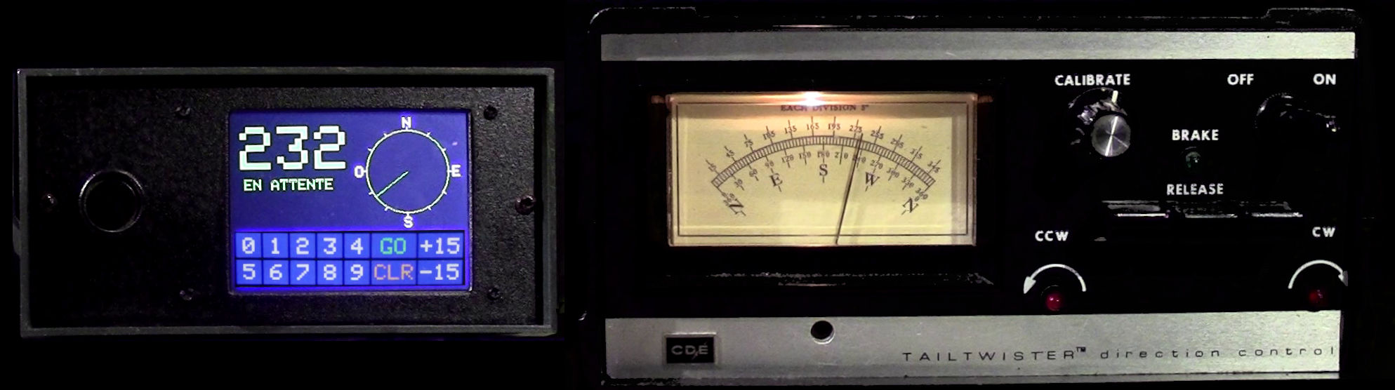
However, the control box has an
outdated interface, with analog
heading indication and manual
orientation and brake release
levers. We are far form a "set
heading and forget" approach here!
Looking around, it is possible to
purchase readily made electronic
controllers, but their prices
(ranging from a few to several
hundred dollars) are unreasonable to
me. I would rather have fun
designing and building a controller
that meets all my requirements, and
at a fraction of the asked price for
a commercial unit.
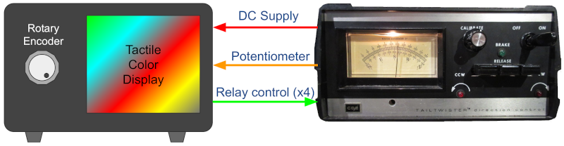
This project details the design and construction of an add-on unit to existing CD-45, CD45-II, Ham-III, Ham-IV and TailTwister rotator control boxes, It brings several desirable features, such as a color touch-screen, a rotary encoder and remote control via a computer. This makes it a real automated unit! No more manual controls...unless you still want to!
Here are the project's main features:
The best way to understand what this project offers is by first consulting the Circuit Schematic of the board below (click on schematic to enlarge): 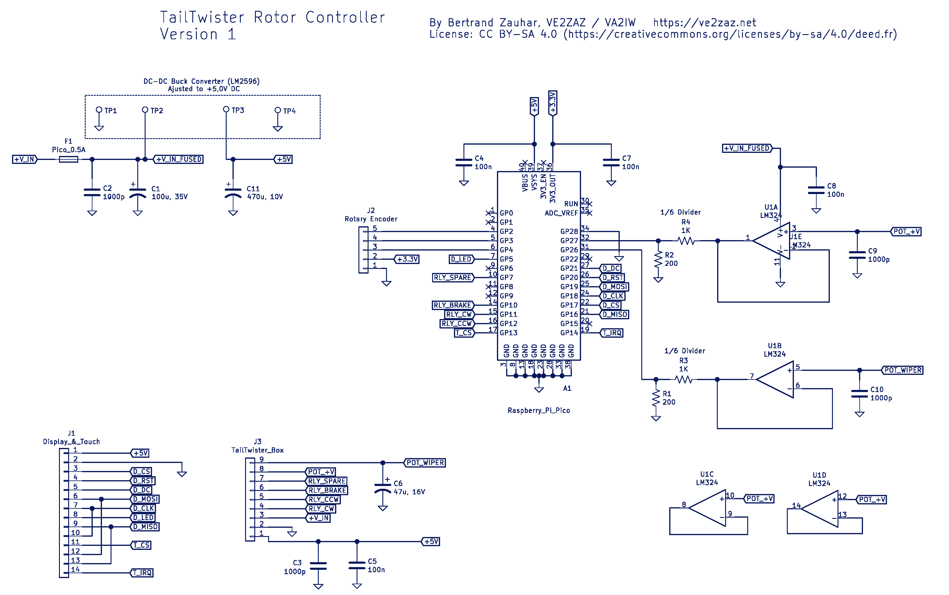
The circuit is rather
straightforward. Here are its main
features.
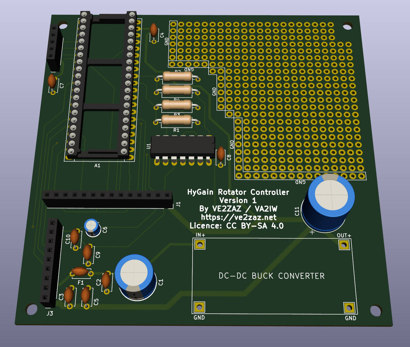
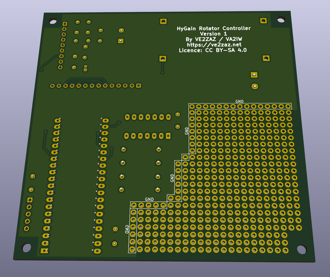
The Printed Circuit Board is a double-sided design, 100 x 100 mm in size, with plated-through holes, solder resist and silkscreen (marking) on both sides. All components are of through hole mounting type. The PCB features a prototyping area, allowing for hardware additions if new features are required. The zip file contains the KiCAD design files. It also contains the Gerber and drill files for anyone who would like to order the PCB. Such PCB can be ordered for around $20 per lot of 5 PCBs. I normally order from JLCPCB, but other major manufacturers will produce the same quality. In your order, select 0.062" (1,6 mm) thickness FR-4 glass-epoxy material, the standard.
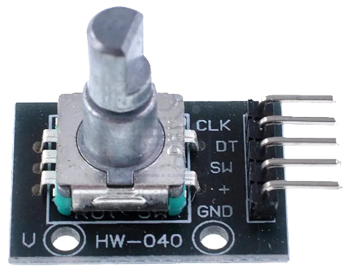
The following is a list of all required components and sub-modules to put together this project. In general, component selection is not critical on this project. As a result, one can order all required components from known local suppliers (Digikey, Mouser, Element-14, etc.), or order from Asian online suppliers like AliExpress, Banggood, DealExtreme, eBay, etc. The latter approach will yield a much lower total cost. On-Board Components
Additional Components and Hardware
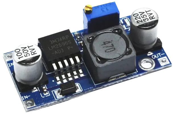
The board is not particularly difficult to assemble by hand. The components are mounted and soldered onto the PCB in a through-hole fashion. A small tip soldering iron and some solder wire is appropriate for the job. Note that the entire circuit operates in a floating fashion with reference to the chassis ground. This is imposed by the internal construction of the rotator, which connects together the pot wiper and the chassis ground. This was done by the HyGain designers to save one wire between the controller and the rotator unit. This limitation forces us to insulate the project from any chassis ground or antenna ground. Although there is no copper contacts around the mounting holes, the use of plastic standoffs to mount the PCB is recommended. This insulation must also be preserved with the USB cable mounting on the enclosure. The DC-DC converter board should be adjusted to a +5 VDC output prior to mounting it to the PCB. Any input voltage from +7 to +28 VDC will be suitable for the task. Mounting of the DC-DC converter board can be done with 4 short wires. It is advisable to leave a 1/8-inch (3 mm) air gap between the converter board and the PCB.
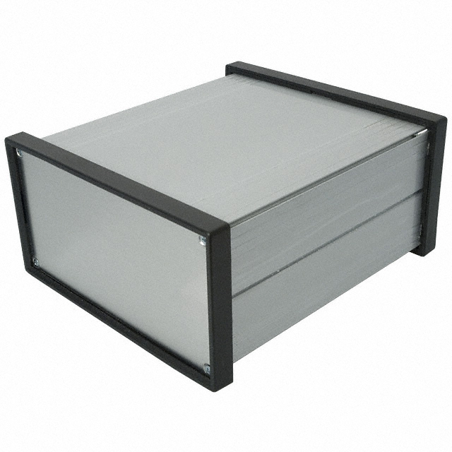
A metal enclosure should be used. This helps to contain EMI radiation from the micro-controller. A suggested enclosure is a Bud Industries EX-4522, 176 x 155 x 80 mm, extruded aluminum box. This is a rather expensive enclosure; it still shows the type of box one may want to use. The enclosure is much larger than the board, and this is suggested to allow easy routing of the internal cabling, and to provide enough front panel surface to accommodate the LCD display. The author recovered an enclosure from another project. This explains where there are holes plugged with aluminum tape on the rear panel. 2025/02/04 Note: There is an issue with the controller when the heading reaches the fully clockwise area during rotation. The displayed heading goes crazy and the controller stops the rotation. This is due, once again, to AC noise super-imposed to the potentiometer wiper signal. Like I wrote above, it was a bad CDE/HyGain design decision to share the ground with the potentiometer wiper signal! The fix to this issue is to add a 220 Ohm, 1/4 W axial resistor in series with the POT_WIPER signal before reaching the controller board. The added resistor, combined with the existing C6 capacitor on the board, creates a low pass filter that eliminated this issue completely. I suggest you add that resistor inside the smart controller box on the wire going to the controller board.
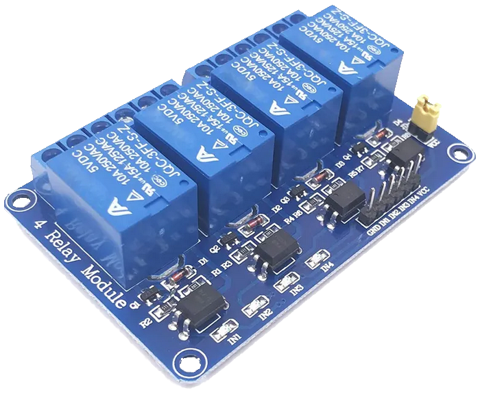
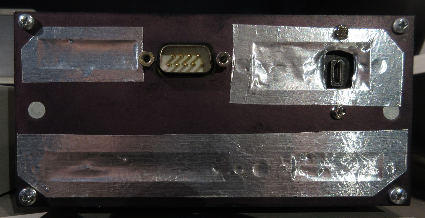
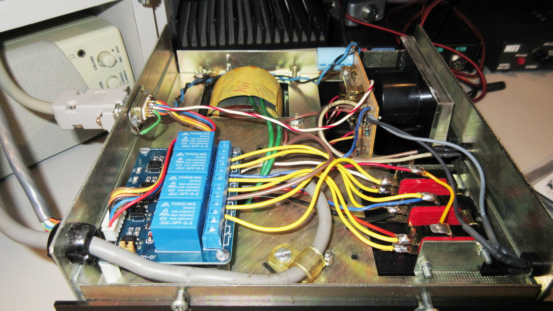
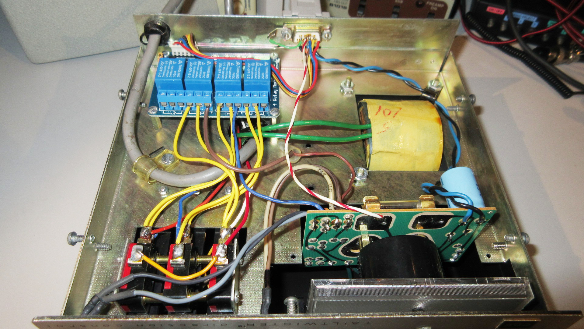
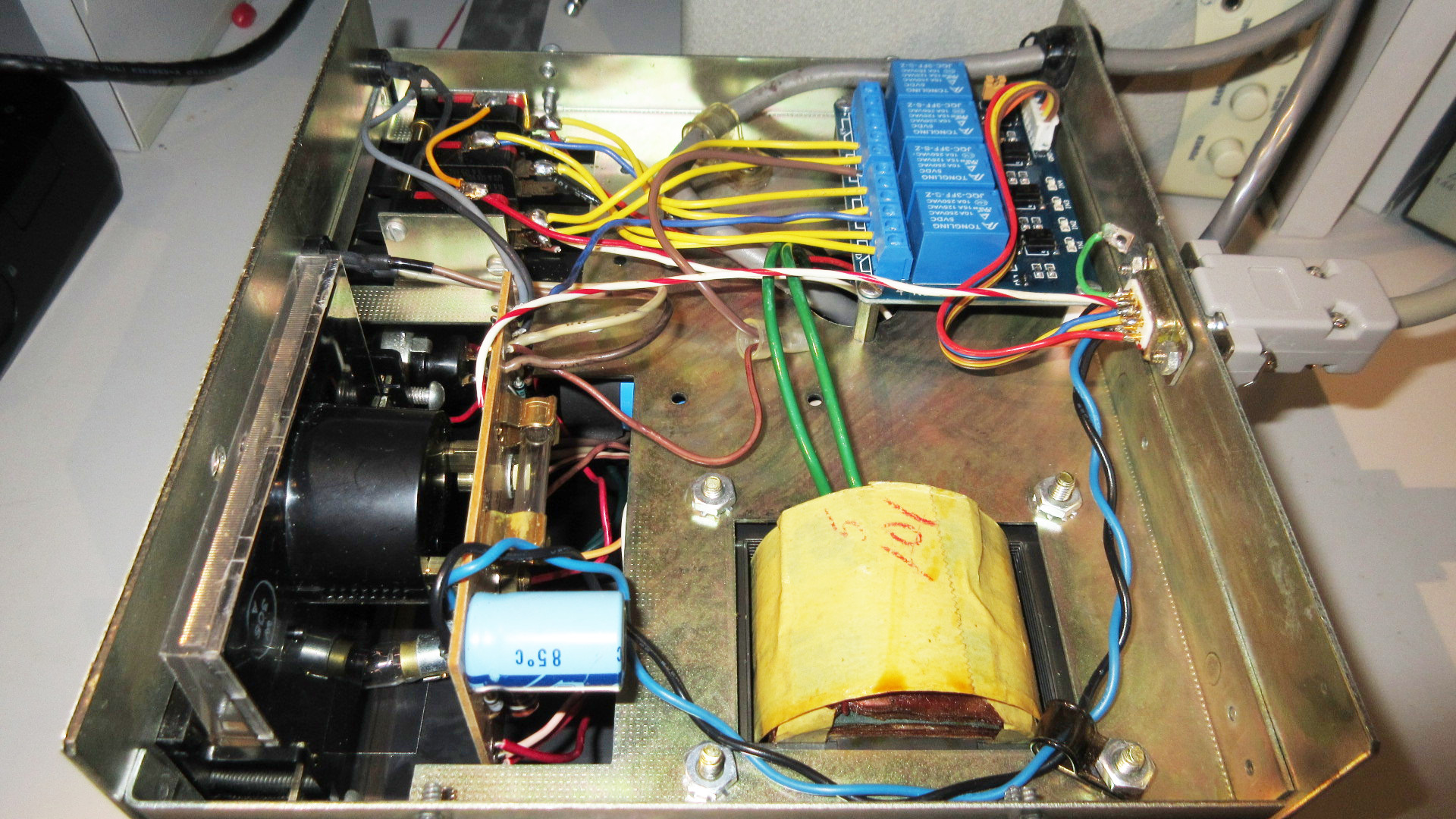
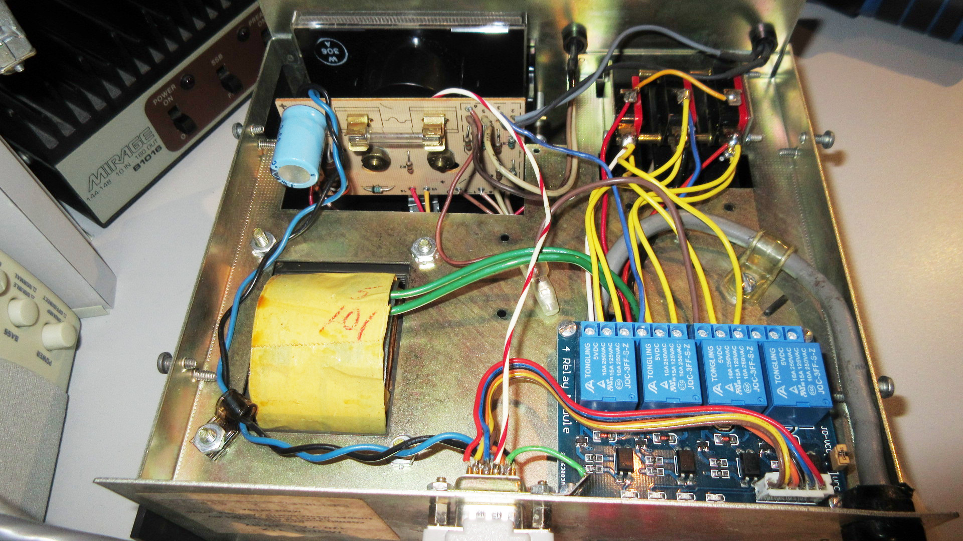
The existing HyGain control box receives the relay board and a female, panel-mounted DB-9 connector. All modifications are performed on the underside of the unit. The unit shown in the images below dates 1980. Newer units may have a slightly different layout. Study the following schematic and pictures carefully. The changes to be made are shown in red color. The changes shown apply to the TailTwister model. For other applicable HyGain models (CD-45, CD45-II, Ham-III and Ham-IV) there are no LED signals to intercept. Consequently, in those units, the add-on relays simply bridge the three micro-switch contacts. 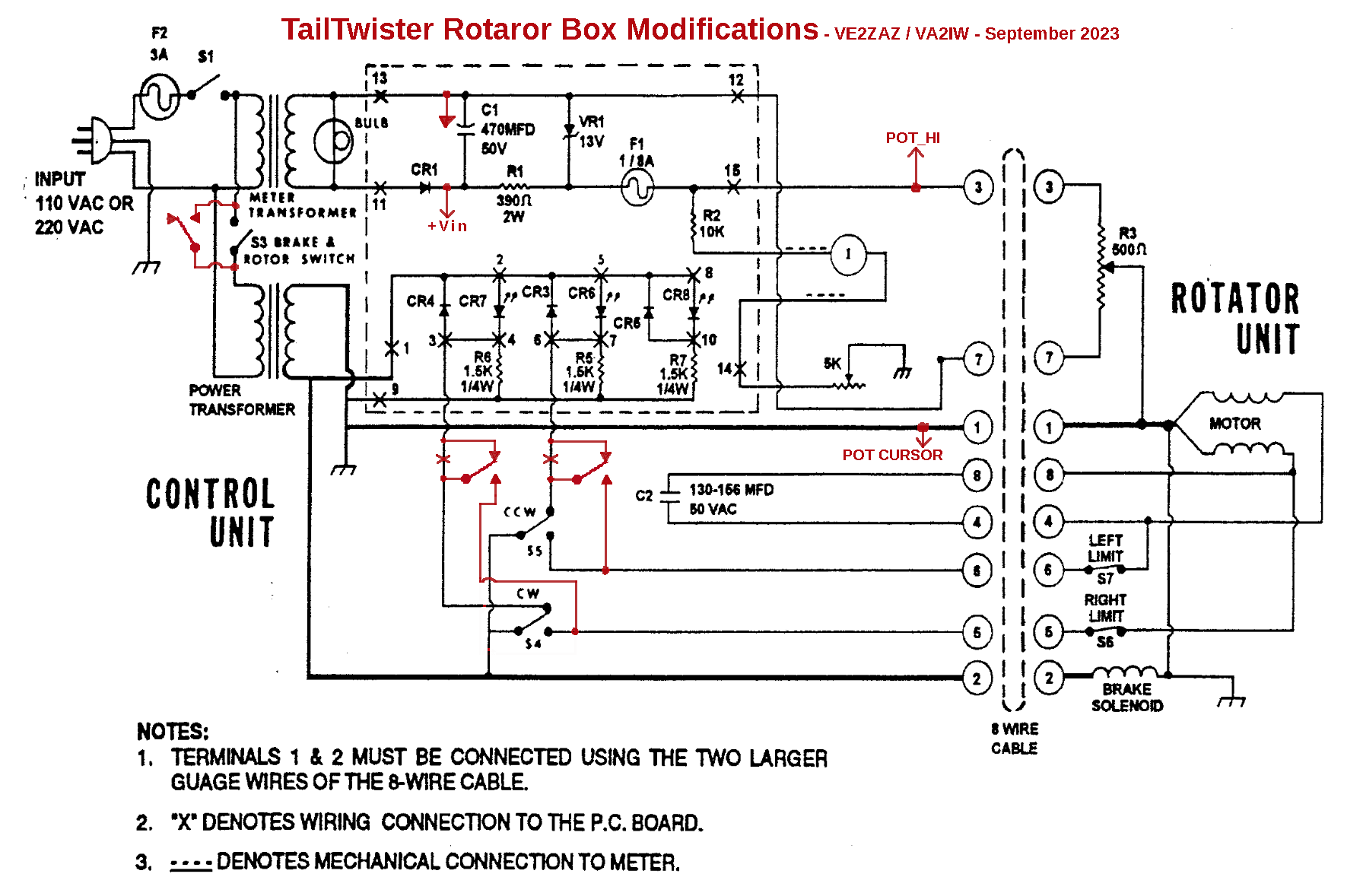
Most control wires (the yellow wires in the pictures above) are soldered directly to the micro-switch lugs. In TailTwister models, the two wires going from the micro-switches to the existing PCB (blue and brown wires in the author's unit) are the LED control wires. They are disconnected from the micro-switches and re-routed to the relay board. These wires may have to be lengthened to reach the relay board. Installation of the female, panel-mounted DB-9 connector onto the rear panel requires a D-shape hole and two small mounting holes to be drilled and filed. The rear panel is made of steel. This makes it a rather labor-intensive job. Signal assignment to the connector pins is arbitrary, but should be made the same at the new controller end. The rotator potentiometer cursor signal is shared with the chassis ground. To hook up the potentiometer cursor signal to the connector, simply connect the chassis ground to one of the pins. This is shown as a short green wire in the pictures above. The +27 VDC supply is picked up directly from the large capacitor on the existing PCB (twisted blue and black wires in the pictures above). Simply solder two wires to the capacitor solder pads, and route them to the DB-9 connector. Make sure to respect the polarity (in the pictures above, the blue wire is the positive lead).
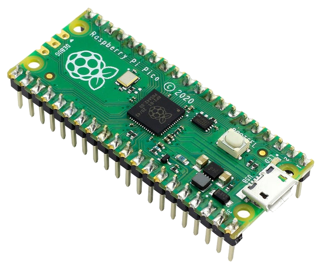
The Arduino firmware is written to be compiled in the Arduino IDE environment. The Arduino IDE software must thus be installed to a computer. The IDE is available for Windows, Linux and MacOS operating systems. Visit https://www.arduino.cc/en/software for more details on how to proceed. Support for the Raspberry Pi Pico must also be added in Arduino IDE. Consult this Instructables link for more details on the prodedure. The Arduino firmware (a.k.a. the sketch) uses the following non-standard libraries:
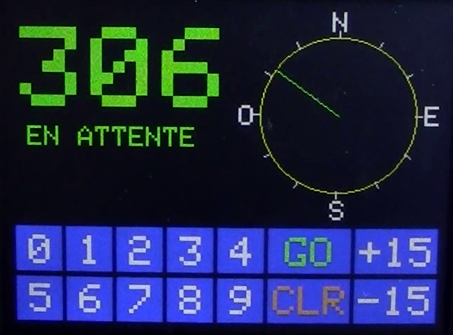
2025/02/04: The latest firmware supports both South-Stop and North-Stop rotator configurations. By default, the firmware assumes a North-Stop setting. Selection of the South-Stop configuration is performed by shorting together pins 2 and 3 of the Raspberry Pi Pico as a permanent connection. Note that the welcome message shown at controller power up now also displays the selected configuration. The Arduino sketch for this project can be downloaded from my GitHub page. Note: Even though the controller display images shown here have French text, the final firmware has English text. Obviously, one can easily change the displayed messages in the firmware to suit his/her preferences.
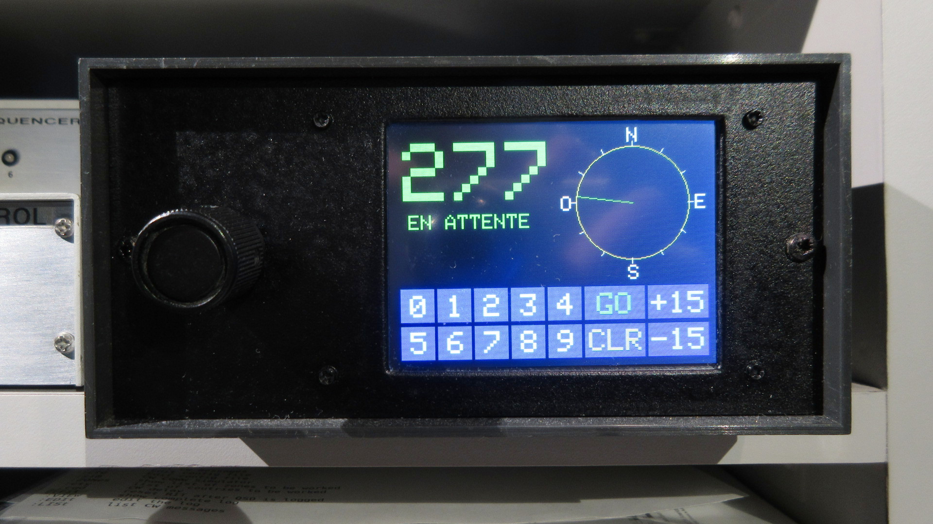
Operation is
simple and fast. When you turn
on the power switch on the
existing box, the new controller
lights up and becomes
operational within a couple of
seconds.
 There
are four ways to re-orient the
rotator to a new heading: There
are four ways to re-orient the
rotator to a new heading:
When entering a new heading using the display keypad, pressing the CLR button will clear the entry. If entering a heading of more than 360, the unit will automatically erase the entry. A computer Rotator Control Software is available to remotely operate the rotator. Re-orienting the rotator can be as simple as a mouse-click on the map. Binaries are available for both Windows and Ubuntu-Linux on my GitHub page. More information on the software operation is detailed on GitHub. 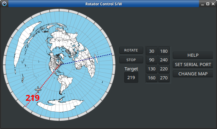 Warning: In order for the unit to be connected via USB to a computer, a USB isolation dongle must be inserted on the USB cable. This is a requirement due to the floating heading indication circuit with reference to the chassis ground. A suitable USB isolator such as the unit shown below can be purchased for a few dollars on online stores. 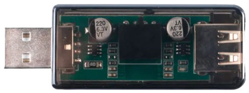 Note that the calibration procedure of the existing control box (bringing the needle to the 360 degree mark) still applies with the new controller.
Although this was not a particularly difficult project to design, one aspect increased the challenge. The existing indication meter circuit operates in a floating fashion with reference to the chassis ground; a separate AC transformer is used just for the indication circuit. Since the pot wiper and the chassis ground are connected together, a lot of 60 Hz AC ripple noise (like 1 Vrms) makes its way onto the potentiometer signals. This is invisible to a slowly moving meter needle, but it sure is problematic for the Raspberry Pi Pico ADC, which samples at more than 500 Kilo-samples per second! To eliminate the effect of that ripple, a long averaging period is implemented in firmware. This averaging nulls out the ripple and derives the actual potentiometer cursor voltage. 2025/02/04: The added 220 Ohm resistor supplements to the AC filtering. I have been operating this controller for a few months. Although there may be improvements to be made, the main objectives are met. It is a joy to re-orient the antennas and not have to worry about holding the brake lever and stopping the rotation at the right moment. And remote operation using the computer software is real joy when contesting! Some of the features do not quite suit you? Make changes to the firmware then! It is very easy in Arduino IDE. The code is fully commented, so you should have no problems understanding what I have done. And there is even a prototyping area on the board to add some additional hardware if needed. Enjoy! |