|

|
|
|
 |
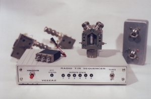
The "At Last!"
Radio TR Sequencer |
|
By: Bertrand Zauhar,
VE2ZAZ
Published in the March
2007 issue of ARRL's QST
Magazine
|
|
|
|
|
Page last
updated: 01/09/2023
|
|
This page complements
article "The "At Last!" Radio TR Sequencer"
published in the March 2007 issue of ARRL's QST magazine.
This page also provides updates to the original
article.
Please visit this page
frequently, and right before assembling the
project, as new information may get added
regularly.
Once again, I would
like to express my gratitude to Jocelyne, my
wife.This project took 6+ months of spare time
to develop, so she deserves it! Also, thanks to Jim-WB4GCS,
Hugh-VA3TO and Dave-W6TE for beta-testing this
system.
Bert, VE2ZAZ
ORIGINAL
QST MAGAZINE ARTICLE
|
For those who have not
read the article yet, this is the best
place to start learning about this
project.
Reprinted with permission. Copyright ARRL,
2007 all rights reserved. This material
originally appeared in QST: Official
journal of the ARRL (www.arrl.org/qst).
|
|
OBTAINING
A
PCB AND PROGRAMMMED PIC MICRO
|
Note:
As of October 2015, I no longer provide the
blank PCB, as the demand cannot justify a
quantity order of PCBs from my part. Sorry for
the inconvenience.
Please contact me via email
if you would like more information on the following item described
in the article:
- A
pre-programmed PIC 18F2220 micro-controller.
I will be happy to provide you
with procurement info in my email reply.
THE LATEST NEWS,
ERRATA AND IMPROVEMENTS
|
(Added 29/08/2008)
Optoisolators Lumex OCP-PCT124 are
no longer stocked by Digikey. You can substitute
with Fairchild LTV-814 (Digikey 160-1344-5-ND) or Sharp
PC814XJ0000F (Digikey 425-2439-5-ND).
(Added 31/07/2008)
A user reported back that the
Firmware Version field under the Settings Transfer
tab of the Windows Setup tool reports version "01"
even though the firmware is supposed to be version "02". I traced back the
problem to a field I did not update in the PIC
program memory back when I compiled version 2.
Please rest assured, all users received a version
2 chip. This is just a display issue. It does not
affect functionality and it does not call for an
increment in the version number. From here on
though, I will ship version 2 chips that display
"02".
(Added 02/04/2007)
I added a note in the Firmware Programming
section to highlight that the 5V In-Circuit
Serial Programming (ICSP) is not supported
on the sequencer PIC firmware load.
(Added 01/04/2007)
The original QST article is now
available for download in PDF form. See above.
(Added
09/03/2007)
Version 1
of the Remote Monitoring tool is now
available for download.
See the software section below.
(Added
02/03/2007)
I am now
shipping version 2 of the PIC
firmware. This version fixes a small bug in
the disarming process. It also adds remote
monitoring capability. A Windows tool will
allow to remotely monitor all 6 output LEDs,
the PTT LED and will produce tones. This
saves a lot of wiring for those who would
like to remotely install the sequencer PCB
(tower-mounted, for example).
I apreciate reading
back from experimenters who build this
project. This allows me to improve this page by
providing additional clarification if necessary.
Thanks!
Due to space
constaints, the top-down view of the
PCB layout was not kept in the QST
article. Here it is for reference
purpose.
Click on the figure to view it in
larger size ->
|
|
|
CONFIGURATION
SOFTWARE (WINDOWS)
|
This is the Windows program that
provides a user-friendly interface to the T/R
Sequencer system to configure it. The software
provides the following features:
- Microsoft Windows-based
program with single window and tabs,
- All
parameters are set up and saved from
within one program,
- Serial
port driven; supports COM1 to COM255,
- Help
provided via mouse cursor hints,
- Only
required at configuration time.
- No installation script;
does not modify the registry or
install DLLs. Just unzip and run .exe
program.
|
|
Version 3 of this software must be
used with version 2 of the PIC firmware
(currently shipping).
This software was developed and
tested in a Windows 2000 environment. It was
also tested in Windows XP, Windows 7 and
Windows 10.
REMOTE MONITORING
SOFTWARE (WINDOWS)
|
This optional
Windows software provides
the ability to remotely
monitor all 6 output LEDs, the PTT LED and
produces tones through the PC sound card.
This saves lots of wiring for those who
would like to remotely install the
sequencer PCB (tower-mounted, for
example). The RS-232 link is used to
accomplish this.
- Provides a visual indication
of Output LEDs and PTT LED status.
- Provides sequence completion
tones, a switching alarm tone and a
timeout tone.
- Microsoft Windows-based
program with a single small window.
- Serial
port driven; supports COM1 to COM255.
- No installation script;
does not modify the registry or
install DLLs. Just unzip and run .exe
program. A program settings
file is saved in the same directory as
the program.
|
|
Version 2 of this software must be
used with version 2 of the PIC firmware
(currently shipping).
This software was developed and
tested in a Windows 2000 environment. It was
also tested in Windows XP, Windows 7 and
Windows 10.
| For
those of you who would like to make their
own "At Last!" Sequencer PCB,
here are the top layer, bottom layer and
top silkscreen layers saved in .PDF
format. The document prints on Letter-size
paper. When printing in full size (no
scaling), the size and proportions should
be accurate. |
|
LEARNING
ABOUT AND PROGRAMMING THE PIC
FIRMWARE
|
If you would
like to look at the firmware load
running inside the PIC
micro-controller, well here it is! The
ASM file is a text file of the source
code I wrote. Beware! This is Assembly
language...The code is well documented
though. Have fun... ;-)
I also provide the latest HEX file
required to upload the firmware load
into the PIC 18F2220's program flash.
This file is in 8-bit Intel HEX
format, which is the industry standard
for 8-bit micro-controllers. Note that
5V In-Circuit Serial Programming
(ICSP) is not supported on this
firmware load. All pins are
assigned to sequencer functions, so
the low voltage ICSP programming
pins could not be spared for that
task. In order to
accomplish the firmware upload, you
need a PIC programmer that can handle
the PIC 18F series chips and standard
high-voltage programming.
Version 2 of the firmware supports the
Remote Monitoring feature through a
Windows program. It also fixes
a small bug in the disarming
process. Updated
18/03/2011: I have
updated the Version 2 files
provided here. There was one
small difference which I had
overlooked. If you tried to
program the PIC with the
previous files, you may have had
problems, with the PIC not
starting up.
|
|
ADDITIONAL
ASSEMBLY
/ WIRING INSTRUCTIONS
|
- The 7805
voltage regulator should be
mounted with its case "grounded". A
small TO-220 heatsink should be
inserted between the PCB and the
regulator case. A good example of a
suitable heatsink is Digikey's
HS107-ND. A small bead of
heat-conductive paste should be
applied to both surfaces.
- In-Shack
Wiring. The
figure
to the right shows how the sequencer
must be wired in order to configure
and operate the sequencer from
within the shack.
- RS-232. The RS-232
connection is a simple 3-wire
communication. No handshaking or
strapping is required at the PC's
end. As well, you do not need to
set any COM port parameters within
Windows; the software sets these
when data exchange occurs.
- LED
wiring is not clear since
the PCB does not have any pin
marking showing proper orientation
during soldering. Here is how the
LED's should be mounted (also see
figure): All
LED's (D3, D6, D9, D12, D14, D18,
D21) should
have their green diode anode
soldered to the square pad. For
Digikey's MV6461A-ND, this is
the longest lead. This
orientation will make the LED's
turn on in green at first power up
(i.e. configuration is still at
default state).
- Remote
Location Wiring. The figure to
the right
shows what a typical remote
installation of the "At Last!" TR
Sequencer looks like. It basically
uses (UTP) unshielded twisted pair
CAT-5 network cable. The data rate
used by the sequencer is 2400 bps.
This slower rate allows to extend
the cable run without any adverse
effect on transmission quality. I
have made test with 200 feet (60m)
of CAT-5 cable and was amazed on how
little signal quality is affected
with that run. I have every reason
to believe that we could double that
length and still get good results.
Since this installation is subject
to strong RF exposure, clip-on
ferrite cores can be used at both
ends to reduce EMI pickup. I
obvioulsy cannot provide any
guarantee that the remote setup will
work under any conditions. The user
may have to experiment with wiring
type, EMI filtering, etc.
|
In-Shack
Wiring
Remote
Location Wiring
 Click
on the figures above to view them in
larger size. Click
on the figures above to view them in
larger size.
|
ADDITIONAL
OPERATING INSTRUCTIONS
|
- Remote
Monitoring
Tool
- In
order for the sequence tones to be heard
through the sound card and PC speakers,
the sequence tones must be enabled on the
TR Sequencer using the configuration
software.
- The
timeout tone feature of the remote
monitoring tool is managed by the tool
itself and is totally independent from the
timeout tone setting on the TR Sequencer.
There are a few more features that are not
documented in the article, that are worth
mentioning here:
- Remote Monitoring
capability. A Windows tool provides
the ability to remotely
monitor all 6 output LEDs, the PTT LED
and will produce tones. This will save
lots of wiring for those who would like
to remotely install the sequencer PCB
(tower-mounted, for example). The RS-232
link is used to accomplish this.
- Configuration
Checksum.
In order to make the
re-configuration process more robust
against noisy RS-232 lines, an 8-bit
checksum is calculated when the Windows
software sends the configuration data to
the sequencer. The PIC firmware
calculates its own checksum based on the
data received and compares it to the
received checksum. If both checksums
match, the new configuration overwrites
the old one in the sequencer, otherwise
the re-configuration does not occur and
a failure message will result in
Windows.
- Auto-Disarm under
a feedback alarm condition. When an
output feedback alarm occurs, the sequencer
freezes the outputs in their current state to
allow the user to troubleshoot the setup and
wiring. It will stay in
that frozen state for a maximum of 3
minutes, after which the sequencer
will auto-disarm to preserve any radio
equipment that could be transmitting. Of
course, the user can manuallly disarm the
sequencer whenever appropriate within this 3
minute delay.
- Auto-Disarm when
transmission reaches 11 minutes. When a
transmission (Tx mode) is kept active for 11
minutes non-stop, the sequencer
will auto-disarm to preserve any radio
equipment that could be transmitting. This is
provided in addition to the Timeout tone
feature and is seen as a "last resort"
measure.
- Debouncing of the
sequencer PTT. The sequencer PTT line
is debounced in software. This provides a
protection against fast transitions that could
lead to radio system malfunction.
- Watchdog.
The micro-controller also has a hardware
watchdog reset feature. In the unlikely event
that the firmware should crash, the built-in
watchdog will reset the micro-controller. This
forces all outputs to go floating (open
state). The maximum time for the watchdog to
kick in is 4 milliseconds.
|
