|

|
|
|
|
 |
A Simplified
GPS-Derived
Frequency Standard |
By: Bertrand Zauhar,
VE2ZAZ / VA2IW
Published in the
September/October 2006 issue of
ARRL's QEX Magazine
|
|
|
|
|
|
|
Page last
updated: 02/03/2024
|
|
This page complements
article "A Simplified GPS-Derived Frequency
Standard" published in the September/October
2006 issue of ARRL's
QEX magazine. This page also provides
updates to the original article.
Please visit this page
frequently, and right before assembling the
project, as new information will get added
regularly. There is also a mailing list that you
can subscribe to to stay updated. See details below.
I would like to
express my gratitude to Jocelyne, my wife.This
project took 8 months of spare time to develop, so she deserves it! Also, thanks to Jacques,
VE2AZX for beta-testing this system.
Bert, VE2ZAZ
ORIGINAL
QEX MAGAZINE ARTICLE
|
For
those who have not read the article yet,
this is the best place to start learning
about this project.
Reproduced with permission. Copyright
ARRL, 2006 all rights reserved. This
material originally appeared in QEX: Forum
for Communications experimenters (www.arrl.org/qex).
Please report
any broken hyperlinks to me. Thank
you.
|
|
GPS_Standard
MAILING LIST
|
The user community
is growing fast! So I have decided to create a
GPS_Standard mailing list. I have noticed that
the level of knowledge of those who assemble the
project is quite broad. So considering the
relative complexity of this project, this is the
ideal forum for exchanging information among
users. I will also answer questions of common
interest so that everyone can benefit. The
mailing list is not flooded with postings, so
you should not fear of getting too many emails. I encourage
you to ask your technical questions there; you
might be surprised of how much the community is
willing to help...
This list is email-based and runs the Mailman
engine. QTH.net
is the host. This is a free, non
advertisement-based service that is maintained
using donations.
You can read the postings anonymously or even
send a post from the list website, but you have
to register (email address required) to receive
emails. The digest-form email is cool because it
combines the the daily emails into a single one.
I hope you join us there. It will be my pleasure
to greet you in!
PCB
and PIC Procurement
As of November 2020, I no longer distribute the
blank PCB and the Pre-programmed PIC
micro-controller, as the low demand cannot
justify a quantity order of PCBs and PICs from
my part. Sorry for the inconvenience.
Component
Procurement Updates
Since Publication
- The 0.1uF
capacitor I specified (478-2472-ND) from
Digikey is now discontinued. Please
order 478-3188-ND, , a
RoHS-compliant equivalent.
- The 1uF
capacitors can be replaced with
478-3195-ND, a RoHS-compliant
equivalent.
- The Bi-color LED (MV6461A-ND)
is obsolete. You can use Digikey part
160-1058-ND instead.
- The
Green
LED can be substituted with Avago HLMP-1540
(516-1301-ND) or
Panasonic LN38GCPX (P607-ND, minimum qantity
is 10).
- The
LTC1485
(LTC1485CN8-ND) can be
replaced with LTC1485CN8#PBF-ND, a
RoHS-compliant equivalent.
- It
has come to my attention that Dual operational
amplifier OPA2705 may be hard to get. A good
substitute available at Digikey is LMC6482 (Digikey
part LMC6482AIN-ND). In fact, you can
substitute the OPA2705 with a dual operational
amplifier that offers the following
characteristics:
- It
must
tolerate the supply rails you will submit it
to (0 to +5V or -5V to +5V, depending on the
OCXO to control).
- It
must
be of the Rail-to-Rail input and output
type, otherwise you will lose some tuning
range. A LM358 is not
a good choice because of this.
- It
must
be able to drive the equivalent capacitance
of the OCXO tuning input pin. In case an
oscillation is seen, a 1K resistor added in
series with the Tuning Output voltage should
dampen any oscillation.
- It
must
(of course) have a DIP-8 package and have
the same pinout.
To help in
generating a Digikey order, I have
created an .xls spreadsheet file with
all the electronic components required
to assemble the board. You will be able
to import this file directly into the
Digikey website and generate an order. I
cannot guarantee that all the components
listed will be available when you order;
you may have to find substitutes. But it
is still a good starting point. Insure that
you remove any of the components that
you already have and/or don't need to
order before submitting the final
order. An example is the
non-programmed PIC18F2220
micro-controller which you may remove if
you don't own a PIC programmer...
|
|
MONTROL
SOFTWARE
UPDATE (Added 06/04/2009)
A minor display
problem was found in the Montrol software
statistics window. Under certain
circumstances, abnormally small Average Offset
values may display. Version 4 of Montrol
corrects this. See the Montrol SOFTWARE FOR
WINDOWS section below
VERSION 4 PIC FIRMWARE UPDATE (Added 18/03/2009)
This
firmware release adds a couple of nice-to-have
features:
- An Alarm Latch clear
push-button feature which allows to clear any
latched alarm without having to log on to the
system via RS-232C. Grounding pin 22
momentarily will clear the alarm latch.
- A 10MHz/5MHz OCXO rate
selection based on the state of pin 21. High
(default, floating) state is 10MHz, Low
(grounded) state is 5MHz. Selection is made at
power up only.
No change to the FLL
functionality is made here. Version 4 (v4) of
GPS_Std firmware can be downloaded below. See the Additional
Assembly Instructions section for more
details on how to wire the system and use the
above features.
VERSION
3 PIC FIRMWARE UPDATE (Added 12/09/2008)
Microchip
has announced a bug in their latest chip
errata. This bug holds the chip in reset
unless the Power up delay feature is turned off.
This applies to chips with date codes greater
than 0813 (2008, 13th week). So a new firmware
is required to be fully compatible with the
newer batch of chips. Version 3 (v3) of
GPS_Std firmware which corrects the issue can
be downloaded below.
VERSION 2 PIC FIRMWARE UPDATE (Added 25/08/2008)
A fault was found
on the PIC v1 firmware when controling 10MHz
OCXO in Voting mode. Version 2 (v2) of GPS_Std
firmware which corrects the issue can be
downloaded below.
MONTROL SOFTWARE
UPDATE (Added 03/07/2008)
A small bug was
found on the Montrol software statistics
window. It will affect those who use a 5MHz
OCXO. All statistics displayed were previously
computed assuming a 10MHz oscillator, Version
3 of the Montrol software now detects when a
5MHz OCXO is used and calculates the stats
accordingly. A couple of additional fixes are
implemented. This update is available in the Montrol SOFTWARE FOR
WINDOWS below.
LOW VOLTAGE GPS
RECEIVERS (Added
20/04/2007)
See the note in the Additional
Hints below
regarding using a low voltage version GPS
Reciver.
MONTROL SOFTWARE
UPDATE (Added 30/09/2006)
A small bug was
found on the Montrol Windows software. It may
or may not affect you, depending on your PC
configuration. An access violation popup
window may show up when trying to change the
COM port using the "Config" button. If you
experience this problem, uninstall your
existing Montrol software and install Montrol
version 2. This update is available in the Montrol SOFTWARE FOR
WINDOWS below.
5MHz OCXO SUPPORT (Added
26/09/2006, updated 18/03/2009)
Following
a request from one of the readers, I have come
up with a firmware release that supports a
5MHz OCXO, as opposed to the more standard
10MHz frequency. Before using this firmware
version, the following considerations have to
be noted:
- I have only run basic
acquisition and lock test with a 5MHz
oscillator. I did not perform long term
accuracy measurements so I cannot provide
any indication on the level of performance
obtained. I have every reason to believe that it
will work well though.
- The output sub-rates will be
2.5MHz and 500KHz, which are odd
frequencies from a frequency standard's
perspective.
- Some software parameters will
have to change for optimized performance.
The user will have to experiment. An
example, for a known Averaging Cycle Size (S), accuracy
will be less; this is obvious since the
measurement resolution of the system
becomes one pulse in 80,000,000 instead of
one in 160,000,000. A longer Averaging
Cycle Size (S) will compensate though.
- I will make no modifications to
existing documentation. Wherever you read
numbers such as 10MHz and 0x6800 (26624
decimal), you should instead read 5MHz and
0xB400 (46080 decimal) if you are using a
5MHz OCXO.
Starting
in v4, the PIC firmware includes built-in
support for a 5MHz OCXO. Previously, the
frequency had to be specified at PIC programming
time.
I would appreciate reading
back from the experimenters who build
this project. This will allow me to improve this
page by providing additional clarification if
necessary. Thanks!
USER
COMMENTS AND END RESULTS
|
This
section regroups comments and end result sent by
some of you who have assembled the project. (Updated
11/05/2007)
- Jacques,
VE2AZX,
was the beta-tester for this project. He did a
pretty good job of integrating the system into
an existing HP 5328A frequency counter with a
built-in HP 10544 OCXO. Jacques provides this
info along with some small mods/improvements
to the PCB and some system spurs and stability
analysis in one zip file available on his
website. Thanks Jacques!
- Jeremy,
AD7MK
led their class project at
the Idaho State University. They decided they
needed a better standard for their lab, so
they procured the PIC micro and PCB. After
project completion, they ran their standard
against a commercial-grade GPS standard
(NIST-traceable) and were impressed with the
results. See their webpage.
| I wrote a
comprehensive user manual that describes
VE2ZAZ's GPS-derived frequency standard.
Topics such as detailed system
description, hardware and firmware
setup, serial port strings and commands
are covered in the manual. This document
is a must if you are looking for the
information on how to put together the
"Simplified GPS-Derived Frequency
Standard". |
|
|
MonTrol
SOFTWARE FOR WINDOWS
|
I also wrote a Windows program
that provides a more user-friendly interface to
the GPS_Std Frequency Standard system. The
software provides the following features:
- Window-based program with
main toolbar and multiple windows,
- Full Monitoring and Control
of the GPS_Std PIC firmware,
- All
parameters read or written in decimal,
- Serial
port logging of system status string
for future analysis,
- Integrated
DAC
plotting feature that graphs the DAC
value as a function of time.
- Statistics
window
with average offset, standard
deviation and min/max values computed.
|
|
This software was developed and
tested in a Windows 98 environment. It was
also tested in Windows 2000 and Windows XP.
Since these operating systems cover two main
branches of Windows (9x and NT), the software
is expected to run in all Windows environments
from Windows 95 through Windows XP.
Note to users: In order for
Montrol to send a new Parameter value to the
PIC, you must enter the
parameter value in the numeric field and then
press the <Return> key. A
Parameter readback will confirm that the PIC
took the new value.
Version
History
Version 4 (April 2009): This version
corrects a minor display problem found in
the Montrol software statistics window.
Under certain circumstances, abnormally
small but non-zero Current and Accumulated
Average Frequency Offset values may display.
Version 3 (July 2008): All statistics
displayed were previously computed assuming
a 10MHz oscillator. Now detects when a 5MHz
OCXO is used and calculates the stats
accordingly. Serial ports COM5 to COM8 are
now supported. The Plot feature is now much
improved.
Version 2 (September 2006):
Corrects an access
violation popup window problem that may show
up when trying to change the COM port using
the "Config" button.
Version
1
(September 2006): Initial Release.
| For those of
you who would like to make their own GPS_Std Frequency
Standard system PCB, here
are the top layer, bottom layer and
top silkscreen layers saved in .PDF
format. The document prints on
Letter-size paper. When printing in
full size (no scaling), the size and
proportions should be accurate.
|
|
- This PCB
can be made of double-sided copper clad
glass-epoxy materal. A thickness of 0.062
inch is typical.
- The copper
patterns reside on the PCB top and bottom
sides.
- The board
layout is designed so that signals jump
from layer to layer using component pins.
The user shall solder all components and
wiring on both PCB sides in
order to allow signals to jump.
LEARNING
ABOUT AND PROGRAMMING THE PIC
FIRMWARE
|
If you would
like to look at the firmware load
running inside the PIC
micro-controller, well here it is! The
ASM file is a text file of the source
code I wrote. Beware! This is Assembly
language...The code is well documented
though. Have fun... ;-)
I also provide the latest HEX file
required to upload the firmware load
into the PIC 18F2220's program flash.
This file is in 8-bit Intel HEX
format, which is the industry standard
for 8-bit micro-controllers. In order
to accomplish the firmware upload, you
need a PIC programmer that can handle
the PIC 18F series chips.
Firmware Version History
GPS_Std v4 (18/03/2009): This firmware release adds
a couple of nice-to-have features:
- An Alarm Latch
clear push-button feature which
allows to clear any latched alarm
without having to log on to the
system via RS-232C. Grounding pin
22 momentarily will clear the
alarm latch.
- A 10MHz/5MHz OCXO
rate power up selection based on
the state of pin 21. High
(default, floating) state is
10MHz, Low (grounded) state is
5MHz.
No change
to the FLL functionality is made here.
Since this firmware version creates a
"universal" PIC able to work on both
10MHz and 5MHz systems, I will no
longer be distribuing a 5MHz firmware
version. Those who wish to use a 5MHz
OXCO must ground the PIC's pin 21 to
enable the 5MHz mode. See the Additional
Assembly
Instructions section below.
GPS_Std v3 (12/09/2008): Microchip have added a
defect in their latest chip errata that
affects newer batches of
PICs. This bug will hold the
chip in reset unless the power up
delay feature is turned off
(configuration bit CONFIG2L, bit
0). This bug is seen on chips with
date codes greater than 0813
(2008, 13th week). So a new firmware
is required to be fully
compatible with the newer batch
of chips. The firmware change is
also fully backwards compatible
with previous batched of chips.
GPS_Std v2 (25/08/2008): Fixes a
problem occuring on PICs
programmed for the 10MHz OCXO
frequency. The issue only affects
the Voting mode. The Summing mode
does not exhibit the problem. This
faulty firmware will cause the DAC
to over-correct the OCXO
frequency, which will lead to a
significant offset from nominal
frequency or could prevent the FLL
from locking. Note:
Those who used the v1 file
previously downloaded form this
site do NOT need to perform the
upgrade to v2, as the bug was
introduced by mistake at a later
date than the v1 file originally
posted here.
GPS_Std v1
(September 2006): Initial
firmware release.
|
|
ADDITIONAL
ASSEMBLY
INSTRUCTIONS
AND HINTS
|
- The 7805 voltage
regulator should be mounted with its
case "grounded". A small TO-220 heatsink
should be inserted between the PCB and the
regulator case. A good example of a suitable
heatsink is Digikey's HS107-ND. A small bead
of heat-conductive paste should be applied to
both surfaces.
- LED D1 and D2
locations do not have any pin
marking showing proper orientation during
soldering. Here is how the LEDs should be
mounted:
- D1
should have its green diode anode soldered
to the pad closest to resistor R3. For Digikey's MV6461A-ND, this is the longest
lead. This orientation will make
D1 come on as red-flashing-off at power up
(assuming a valid 1PPS signal is fed to
the system).
- D2
should have its anode soldered to the pad
closest to resistor R9. For Digikey's MV5477C-ND, this is the longest lead. This
orientation will make D2 come on as green
at power up.
- Need a -5V
supply? Do you use a
MAX-232 TTL-to-RS232
conveter chip in the system? Here is an
easy way to generate a -5V supply for the
filter stage operational amplifiers U5A and
U5B. Tap off the -10V charge pump supply
from the MAX-232 TTL-to-RS232 conveter chip.
Pass it through a 79L05 voltage regulator,
Voilà! The amount of current available is
limited though. Since the operational
amplifiers' quiescent current is much less
than 1mA, this leaves us with a few
milli-amps of current to drive the VCXO.
Check that the VCXO input tuning pin draws
little current, a couple of milliamps
maximum. Otherwise, the RS-232 negative
voltage level will sink. This is not a
problem with the HP oscillators since their
tuning voltage input has an impedance of
greater than 100K ohms.
- Low-voltage GPS
Receivers: One user reported problems
locking his 10MHz OCXO to a GPS receiver. The
system would remain permanently in Holdover
state, with wildly varying frequency samples
as opposed to the more typical 26624 (0x6800)
value. It ended up being an insuffucient
voltage swing on his Motorola M12M's 1PPS
signal. Always make sure that the PPS swing of
your GPS is of TTL-grade with at least +4V on
the high state, otherwise add some buffering.
A NPN/PNP tansistor pair in cascade is a good
way to restore the required swing for the PIC
microcontroller.
- Alarm Latch Clear
Pushbutton: In order to use the Alarm
Latch clear push button feature introduced in
the v4 firmware, a momentary
SPST, normally open push button must
be wired between PIC U4-pin 22 and any ground
point in the circuit. No pull up resistor is
required as there is an internal one assigned
to the pin. Momentarily pressing on the
pushbutton will clear any latched alarm. Of
course, if the system is in Unlocked state,
this action will have no effect.
- 10MHz / 5MHz OCXO
frequency selection: Beginning
in the v4 firmware, it is possible to switch
to a 5MHz OCXO frequency instead of the more
common 10MHz. A connection of U4-pin 21 to any
convenient ground point must
be made for 5MHz selection. By
default, when the pin is left unconnected, its
state is high and the 10MHz frequency is
selected. No pull up resistor is
required as there is an internal one assigned
to the pin. The pin state is sensed by
firmware only at power up. Toggling this pin
during normal operation will have no effect.
COMMENTS ON
FLL PARAMETERS
|
I have spent several months
analyzing system performance using various
parameter settings and with various 10MHz VCXO
end-to-end tuning ranges. Here, I make a few
recommendations for those of you who don't have
the time or capability to measure frequency
accuracy. Following these recommendations should
put you in business. I must repeat here that these are
only suggestions and that the users may
find values that better suit their setup. There
are no definite answers, only trends...
System Status-Dependent
Parameters
Condition
|
Averaging Cycle Size
(S)
|
Frequency Averaging Mode
(M)
|
Frequency
Chg.
Negate Threshold
(N)
|
System in Initialization
(Acquisition). This condition is normally seen
after power up form a cold start. Using
a sampling cycle size S of 10
provides a frequent DAC adjustment rate
to quickly reach FLL equilibrium state
(no more repetitive frequency
adjustments in the same direction). The
M of 2 (Sampling Summing mode) provides
a more accurate trend feedback to FLL.
|
10
(0x000A)
|
02
|
02 or 03
|
System in Locked state (Stable).
This
setup is normally engaged after FLL
equilibrium is achieved. Using a longer
S sampling cycle size and a M of 1
(Sampling Voting mode) will allow to
obtain optimized frequency accuracy. The
system should normally be set as such
for long term operation.
|
675
(0x02A3)
|
01
|
05 or 06
|
VCXO Dependent Parameters
Condition
|
Coarse/Fine
Threshold
(F)
|
VCXO
Tuning Slope
(X)
|
| VCXO's with 1Hz end-to-end
Tuning Range. These are oscillators that do
not really require a 14-bit DAC tuning
granularity to achieve optimum frequency
accuracy. Setting F to 01 will
effectively disable any fine frequency
adjustments. HP's 10544 and 10811 series
OCVCXO's are of this type.
|
01
|
|
| VCXO's with 10Hz end-to-end
Tuning Range. These are oscillators that
definitely require a 14-bit
DAC tuning granularity to achieve
optimum frequency accuracy. The value
shown is for a long averaging cycle size
parameter S, like 675. |
08
|
|
| VCXO's with
positive tuning slope. An
increased DAC tuning voltage will generate
a increase in 10MHz output frequency.
|
|
01 |
| VCXO's with
negative tuning slope. An
increased DAC tuning voltage will generate
a decrease in 10MHz output frequency. HP's 10544
and 10811 series OCVCXOs are of this
type. |
|
02 |
GPS-Related Parameter
Condition
|
Holdover Limit
(H)
|
Garmin GPS-25 /
35. This unit
has spurious 1PPS frequency deviations
that require a careful Holdover Limit
parameter H setting. Refer to
GPS receiver behavior comments below.
|
06 to
08
|
Motorola Oncore GT+. This unit
has larger sample-to-sample frequency
deviations and require a larger Holdover
Limit parameter H setting to avoid
getting false Holdover transitions. Refer to
GPS receiver behavior comments below.
|
18
to 24
(0x12 to 0x18) |
COMMENTS ON
STABILITY AND ACCURACY
|
The bottom line accuracy is the
result of several factors. The two most
important ones are GPS 1PPS accuracy and VCXO
stability. We know that the worst case accuracy
of the 1PPS is 10-6. In practice
though, short term GPS 1PPS accuracy is more
like 10-7. Obviously, the longer you
integrate the 1PPS GPS signal for, the better
the accuracy will be. But the drawback of this
is that the longer the integration time
(averaging cycle), the more the VCXO will (or
might) drift. Of course, the better the VCXO,
the more stability you will get. But the overall
bottom line system accuracy equation is
challenging to specify, let alone quantify.
I have measured on several
occasions my system going into the low 10-11
and even high 10-12, but it did not
stabilize there. Eventually, the VCXO drifted or
the 1PPS pulled it away from there. I have made
observations over several months, and concluded
that the 10-10 decade (from 10-10
to 10-9) is a reasonable expectation
from this system. Trying to shoot for better
than this range would mean stretching the
integration time to an impractical duration.
Other disturbances like holdover and power
outages would constantly interrupt your
averaging cycle and make the FLL more or less
useless. I found that an averaging cycle of a
few hours is a good compromise. I guess it is
like everything else in life: A good balance is
the key!
Another contributing factor to
stability/accuracy is voltage regulation as a
function of load current on the +5V regulator. A
+5V variation will impact the PWM output
amplitude on the PIC micro. It will also impact the
offset applied to the operational amplifier to
shift the tuning voltage negative in the case
where you control a VCXO with a -5V to
+5V tuning range.
The single biggest
contributor to load variation on the 7805
regulator is change to the 10MHz output
terminations. I have seen variations of a few
parts in 10-10 when disconnecting
instruments form the system. The workaround to
this (assuming this variation affects you) is to
always put 50 ohm terminations on unused
outputs. When adding an instrument, remove the
BNC termination and connect the instrument. This
will maintain a nominal current consumption on
the output driver chip. Obviously, you will want
to set the controller so that the outputs are
always on. Other current consumers, such as the
LED, the input driver and the decade counter do
not affect stability in a meaningful manner.
There is no doubt in my mind that some things
could have been done differently to improve
performance. I could have used an external DAC
chip, I could have used an external voltage
reference, I could have split the supplies with
two or three regulators, and so on. This might
have improved stability somewhat and would have
made the board bigger and more expensive to put
together. The original goal though was to keep
the design as simple as possible, while still
achieving 1x10⁻⁹ or better accuracy.
That being said,
those of you who operate a tuning voltage from
-5V to +5V (and this is the case with the HP
oscillators) - should try to center the tuning
voltage at or close to 0V. It can be
mathematically demonstrated that this is where
the effects of the +5V voltage variations cancel
out. For applications that require a 0 to +5V
tuning voltage, obviously, the closest to 0V,
the better.
|
COMMENTS ON
GPS RECEIVER BEHAVIOR
|
This GPS-derived
frequency standard allows to perceive some
differences in behavior
of the GPS
receivers 1PPS signal. Differences become visible
when plotting the measured frequency samples (over
16-second windows, as provided by the system) when
the system is in locked state and is stable. These
differences result of different firmware
algorithms used by different GPS vendors. After
analyzing the cases below, the user will better
understand the reasons for having a FLL Holdover
state and the way to figure out what value to
assign to the the Holdover Limit parameter H. I strongly recommend
doing the same exercise for anyone using a
different GPS receiver than the ones listed below.
The first graph shows the Garmin GPS-25 / 35
firmware behavior for its 1 PPS signal when hooked up to the
GPS-derived frequency standard.
From the graph above, the following observations
can be made:
- There is a large frequency
deviation (sudden unexpected frequency
increase) caused by a spurious slow down of
the 1PPS GPS frequency. This kind of deviation
occurs once or twice per day, on average. Note
that frequency deviations in both directions
are seen on the Garmin GPS-25 / 35 1PPS signal.
- The GPS-Derived Frequency
Standard software must reject the frequency
samples during this large deviation, otherwise
the whole averaging calculation will be
erroneous. This is where the FLL Holdover
states becomes useful!
- Not considering this large
deviation, the sample-to-sample frequency
deviation stays roughly within +/-5 of nominal
frequency (26624). This is considered to be
regrouped. Medium-to-long averaging cycles
should yield good system accuracy.
- The plot should give the user
an idea of what value to assign to the
Holdover limit parameter H. For this example,
a Holdover Limit H ranging from 6 to 8 should
provide good imunity to these spurious
deviations, while still letting all good
samples through.
Our second example shows the
behavior of the Motorola Oncore GT+ firmware for
its 1PPS signal when hooked up to the
GPS-derived frequency standard.
From the graph above,
the following observations can be made:
- Unlike the GPS-25 / 35 GPS, there is no large frequency
deviation caused by a spurious variation of
the 1PPS GPS frequency. With a GPS unit like
this one, it is less critical to have a
Holdover limit parameter H set quite tight
compared to the sample-to-sample deviation
spread.
- On the Motorola Oncore GT+ GPS
, the sample-to-sample frequency deviation
stays roughly within +/-16 of nominal
frequency (26624). This is considered quite
spreaded. With such a GPS receiver, for
statistical reasons, a short averaging cycle
is meaningless when trying to achieve optimal
system accuracy. Only long averaging cycles
will yield good accuracy.
- The plot should give the user
an idea of what value to assign to the
Holdover limit parameter H. For this example,
a Holdover Limit H set to 18 or higher should
provide good imunity to any unexpected
spurious deviations.
Note that, while
some of these behaviors may look like GPS
receiver defects, the frequency deviations still
stay within the expected automotive-grade GPS
accuracy of 10-6 (1ppm).
TTL-RS232
CONVERTER REFERENCES
|
You will most
likely want to make your own TTL-to-RS-232
bi-directional converter to interface with the
GPS_Std system and your GPS board. Here are a
couple of useful web references:
The project
started with a wish to make a GPS-derived
Frequency Standard based on frequency
measurement, as opposed to phase
measurement, which is more complex in terms
of hardware. Hopefully, a simple
micro-controller would do the trick.
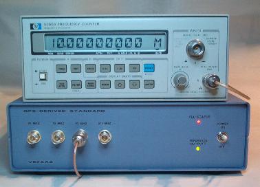
In order to demonstrate the feasibility of
such design, I build an instrument-based
system controlled over GPIB using Labview,
my all-time favorite control software. The
figure below shows the instrument setup.
Pretty quickly, it became obvious that it
would work.
Selecting the right micro-controller was the
next thing to do. I elected to use a Microchip
PIC 18F2220. It had built-in synchronous
counter incrementing and latching via external
signals, exactly what I needed! Though it
lacked a DAC, it had a pretty decent Pulse
Width Modulator that could produce a variable
DC output with a suitable external low-pass
filter. It also had serial port support. I had
all I needed to make this project a success.
Writing the firmware (software) was definitely
the most tedious part of the story. All in
all, I spent six months testing it, analysing
the results, and increasing its functionality.
As a side activitiy, I designed a PCB to host
the components, built a prototype to prove it.
I also wrote a Windows software to monitor and
control the system in a more user-friendly
ashion. I finally wrote a user manual, a
magazine article and this web page.
Honestly, the results are gratifying. I am
quite happy with the final system. I hope you
can sense the amount of perfectionism I put in
that project.
|